00195427-02_AI_HeadReconfigKitsD1D2_DE+EN.pdf - 第67页
Assembly instructions Head Re configuration SIPLACE D 1 / D2 Edition 03/2007 65 2.7.6 Assembly of P&P placement head – 4 f ixing screws: DIN912 M4x16 - 8.8 ( 03052012-) Always use the st andard tool. Use the adjust a…
Assembly instructions Head Reconfiguration SIPLACE D1 / D2
Edition 03/2007
64
2
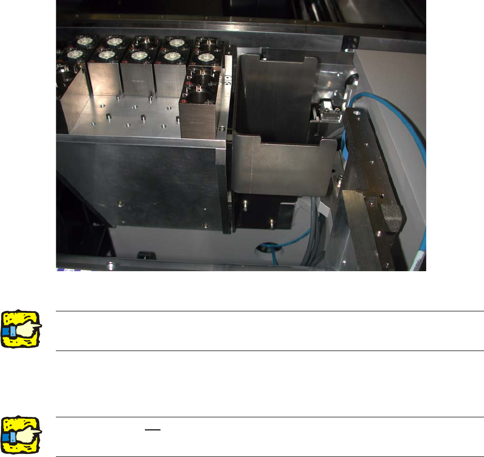
Fig. 2.7.7 Assembled nozzle changer and component reject bin holder
2
: Compare the positions of these magazines with those configured in SIPLACE Pro and reposi-
tion if necessary. The magazines must be screwed tight.
2
: Mount the "Reject bin for P+P head" (03046974-).
2
2
The nozzle changer is provided with 3 "Magazines, complete / 2 nozzles P+P / S-F-D"
(03048676-) and one "Magazine, complete / 1 nozzle P+P / S-F-D" (03048639-) as standard. 2
2
2
The magazines are not compatible with those of the X-series. They have higher placed position
marks and the fixing holes are drilles otherwise. 2
Assembly instructions Head Reconfiguration SIPLACE D1 / D2
Edition 03/2007
65
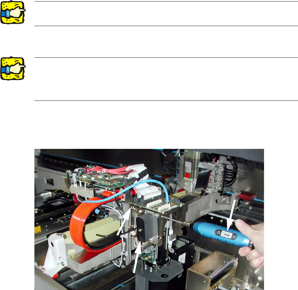
2.7.6 Assembly of P&P placement head
– 4 fixing screws: DIN912 M4x16 - 8.8 (03052012-)
Always use the standard tool.
Use the adjustable torque screwdriver with pivot extension inse
rt bit for placement heads! 2
2
: Remove both screws of the silencer (to reach the screw with the long insert bit) (see Fig. 2.7.8).
2
: Fix the P&P head with 4 screws DIN912 M4x16 - 8.8 (03052012-) and tighten crosswise with
270 Ncm.
2
Fig. 2.7.8 Fix the head with the torque screwdriver
2
: Screw the silencer tight again (2 screws M4x14).
2
2
2
2
Make sure that the screws are of the right length.
Do not confuse the screws of the placement head with those of the silencer!
The thread in the head plate can be damaged if screws with other lengths are used. 2
Tightening torque for the fixing screws: 270 Ncm. 2
Assembly instructions Head Reconfiguration SIPLACE D1 / D2
Edition 03/2007
66
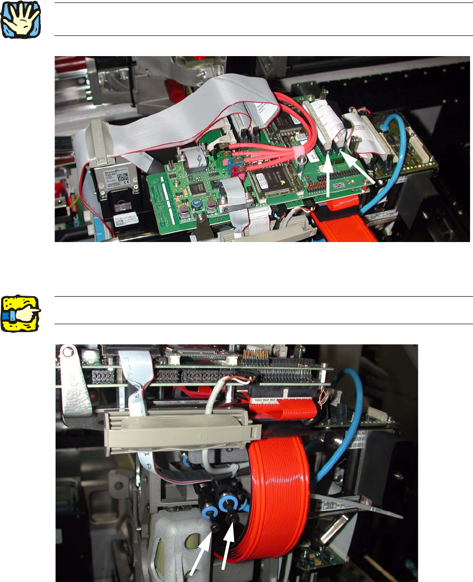
: Establish both electrical connections.
2
Fig. 2.7.9 Connect the 2 ribbon cables of the P&P Modul
: Insert the 2 hoses in the T-pieces.
2
Fig. 2.7.10 For single head: T-pieces with blind plugs
2Cable routing must take place as described in the service instructions D1/D2, FS 03, chapter on
cable routing! 2
2If only one head is assembled, the T-pieces must be sealed with blind plugs. 2