00195427-02_AI_HeadReconfigKitsD1D2_DE+EN.pdf - 第69页
Under no circumst ances, must blind plugs an d ot hers be able to make cont act with the ribbon cable - also not in the end position. 2 Assembly instructions Head Re configuration SIPLACE D 1 / D2 Edition 03/2007 67 2 2 …
Assembly instructions Head Reconfiguration SIPLACE D1 / D2
Edition 03/2007
66
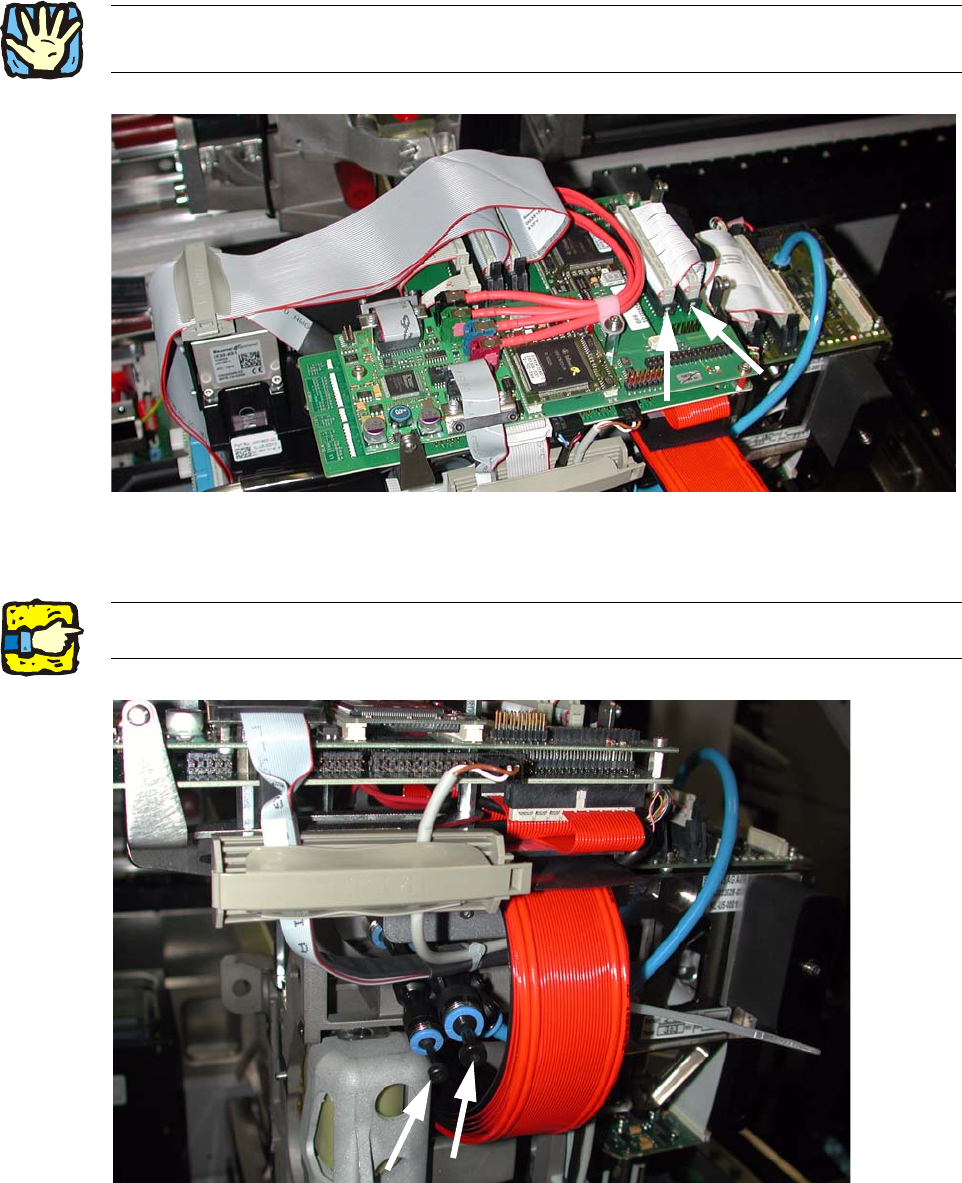
: Establish both electrical connections.
2
Fig. 2.7.9 Connect the 2 ribbon cables of the P&P Modul
: Insert the 2 hoses in the T-pieces.
2
Fig. 2.7.10 For single head: T-pieces with blind plugs
2Cable routing must take place as described in the service instructions D1/D2, FS 03, chapter on
cable routing! 2
2If only one head is assembled, the T-pieces must be sealed with blind plugs. 2
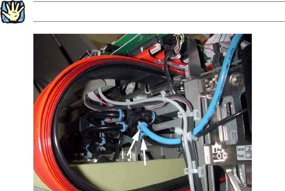
Under no circumstances, must blind plugs and others be able to make contact with the ribbon
cable - also not in the end position. 2
Assembly instructions Head Reconfiguration SIPLACE D1 / D2
Edition 03/2007
67
2
2
Fig. 2.7.11 Connect 2 pneumatic hoses
2
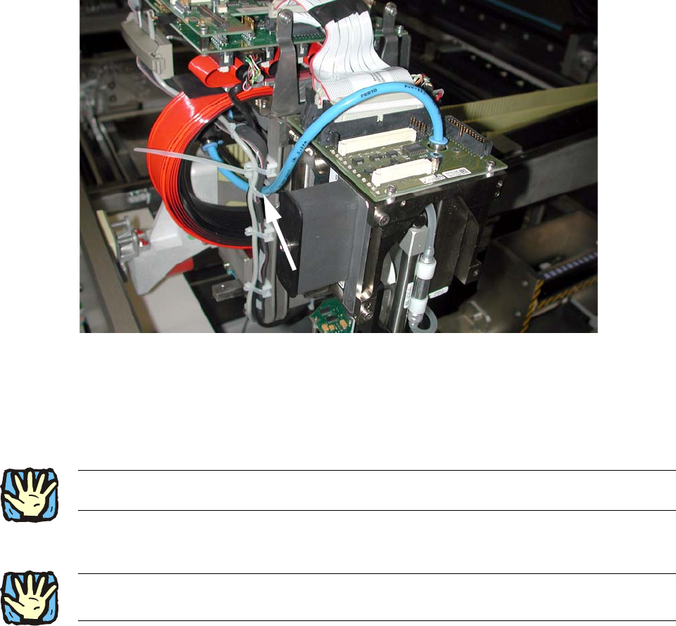
: If necessary shorten the two hoses to the head to the extent that the plugs have no contact
also in the outermost gantry position. The hoses must not kink however!
2
2
2
2
2
2
2
2
2
2
2
Assembly instructions Head Reconfiguration SIPLACE D1 / D2
Edition 03/2007
68
: Fix the silicon hose size 8 and the silicon hose size 6 as shown.
2
Fig. 2.7.12 Fix hoses
2
2.7.7
Wear an ESD armband for the whole time you are working on the placement head and servos! 2
Replacing the servo cards
: Use the machine key to open the door of the servo unit.
2
2
2
2
2
2
2
2Place the axis and servo cards in accordance with your machine configuration.
See the diagram in the annex (Chapter 2.9.1). 2