00195427-02_AI_HeadReconfigKitsD1D2_DE+EN.pdf - 第77页
Assembly instructions Head Re configuration SIPLACE D 1 / D2 Edition 03/2007 75 2.8.4 Hotlink card connections (Computer unit) Hotlink cable labeling Hotlink card for cameras in P A 1 FC camera X3pr IC camera X2pr PCB/co…
Assembly instructions Head Reconfiguration SIPLACE D1 / D2
Edition 03/2007
74
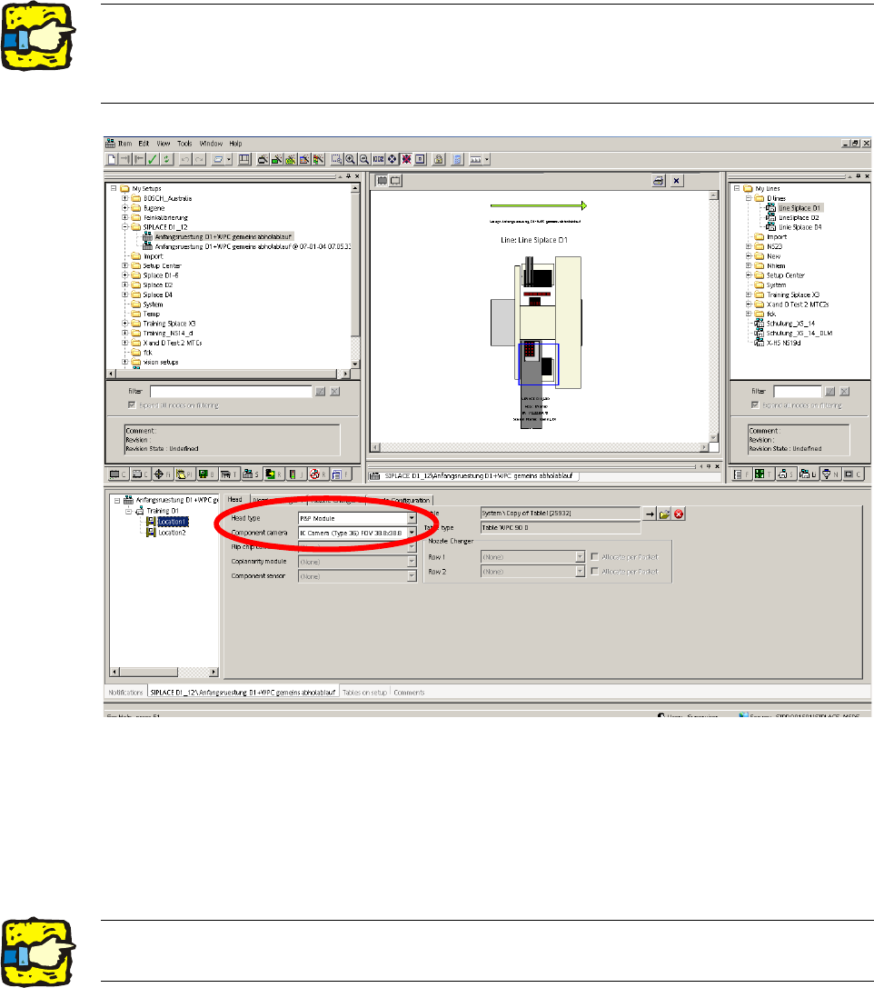
2.8.2 Configuring the C&P head with SIPLACE Pro
: Go to 'Setup editor' —'Location'—'head tab' and enter the C&P placement head.
2
: Reoptimize the set-up in SIPLACE Pro.
2.8.3 Installing the nozzle changer
: To fit the nozzle changer, please read the Assembly instructions for the nozzle changer C+P-
Bestückkopf_SIPLACE_D1-D2 (00195370-).
2The nozzle changer for the P&P head must be configured as row 1the appropriate location. 2
For a D1S for a location without placement head, "none" must be entered for head type and noz-
zle changer. 2
2Risk of a head crash: Always run the placement heads with the appropriate nozzle changer.
The wrong nozzle changer causes a risk of a head crash. 2
Assembly instructions Head Reconfiguration SIPLACE D1 / D2
Edition 03/2007
75
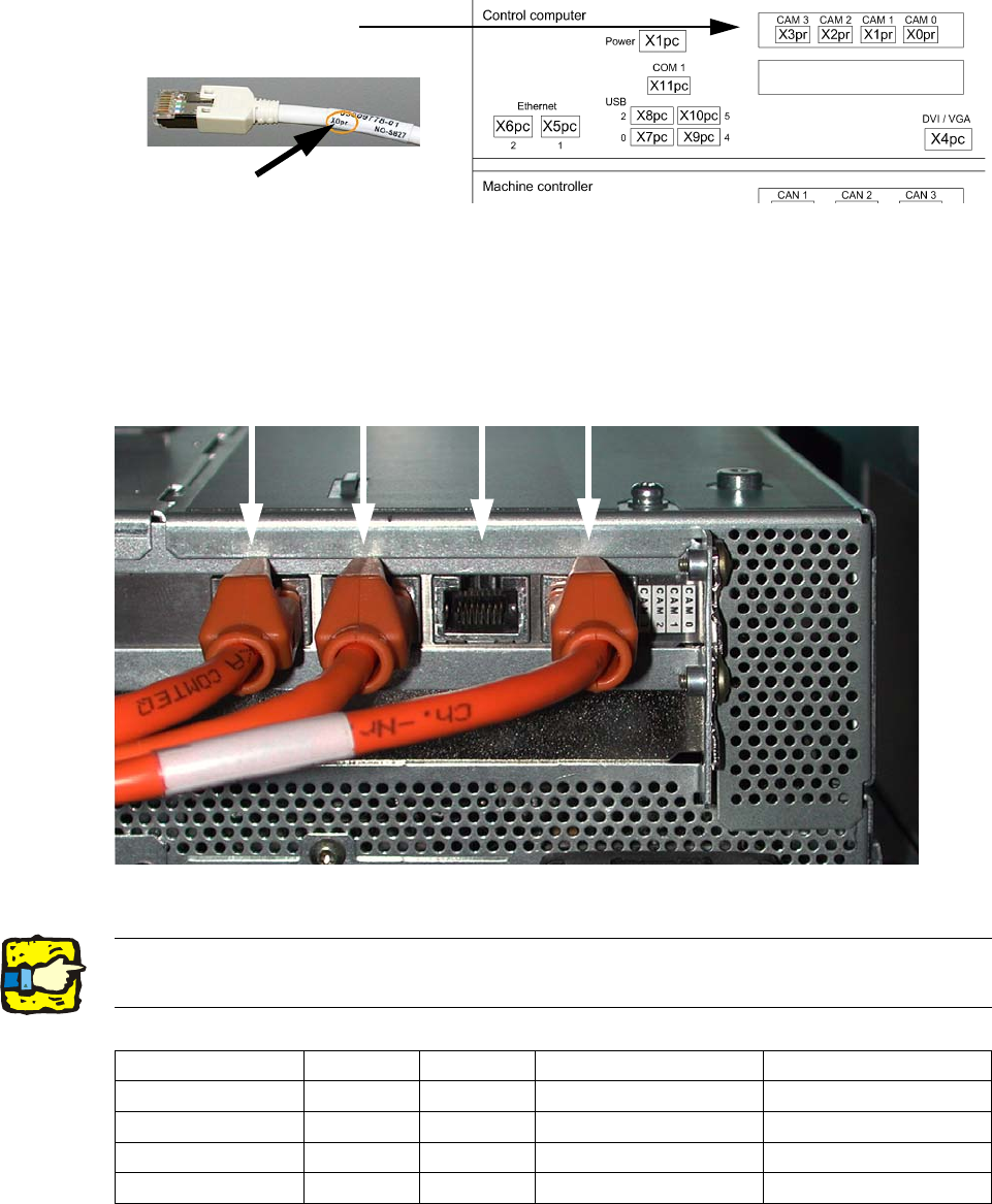
2.8.4 Hotlink card connections (Computer unit)
Hotlink cable labeling
Hotlink card for
cameras in PA 1
FC camera
X3pr
IC camera
X2pr
PCB/components
camera
Gantry 2, X1pr
PCB/components
camera
Gantry 1, X0pr
2
Fig. 2.8.1 Terminal pin assignment Hotlink card
2
2Hotlink cables that are not being used must not be plugged in !!!
Do not confuse hotlink cables with twisted pair cables !!! 2
X3pr X2pr X1pr X0pr
D1
FC camera IC camera --- PCB-/Comp camera, P 1
D1 S (C&P head
--- --- --- PCB-/Comp camera, P 1
D1 S (P&P module)
FC camera IC camera --- X
D2
--- --- PCB-/Comp camera, P 2 PCB-/Comp camera, P 1
Assembly instructions Head Reconfiguration SIPLACE D1 / D2
Edition 03/2007
76
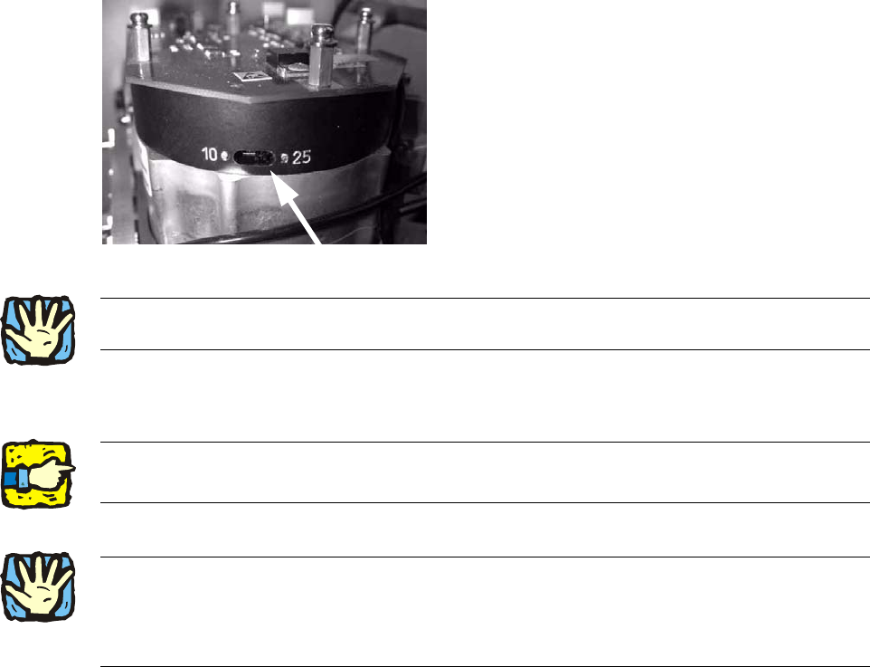
2.8.5 Assembly of C&P6/12 placement head
Handle the sleeve with the utmost care! 2
Make sure that the screws are of the right length. 2
The thread in the head plate can be damaged if screws with othe
r lengths are used. 2
Tightening torque for the fixing screws: 270 Ncm. 2
2
2
2
: Set the switch for the resolution of the star axis to 25.
The switch is located on the underside of the placement head.
2
2
: Remove a sleeve from the star.
: Turn the star so that it moves easily towards the screws.
2
2
2
2
2
2
2
2
2
2
2Always use the standard tool!
Use the adjustable torque screwdriver with pivot extension insert bit for placement heads! 2
2
2