OM-1455-004_w.pdf - 第35页
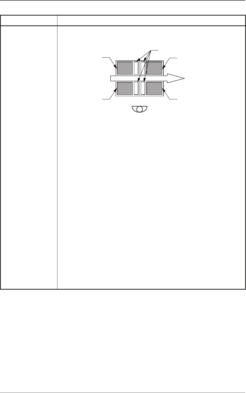
1-4 Tg1576-ID-SO 0708-002 1.1 Specications T able A1-4 Item Description 14. Specied Positi on and T ype The installation locations for the single-transfer tray feeder have been set as follows. FP-G400 FP-G400 FP-G400 F…
1-3
Tg1576-ID-SO
0709-003
1.1 Specications
Table A1-3
Item Description
8. Power Supply DC24V (10W) is supplied from the GXH series main machine.
(It is supplied from the drawer connector on the feeder base).
9.
Air Pressure 0.45 MPa (4.6 kgf/cm
2
)
Note :
Use the dry and clear air as follows.
Water
: Dew Point - 17
°C or less
(Atmospheric Pressure)
Oil :
0.1 mg/m³ or less (ANR)
Dust : Solid Material 0.01
µm or less
(The air is supplied from the main body of GXH Series.)
10. Air Consumption
Approx. 0.2 L/min (Normal)
11.
Mass Single Tray Feeder : Approx. 26 kg
(The total mass of magazines is excluded.)
Tray Magnet : Approx. 25 g
Magnet Attachment : Approx. 2 g
Single Tray Feeder Stand : Approx. 8 kg
12. Dimensions
Single Tray Feeder :
Approx. 415 (width) ×
770 (depth)
× 390 (height) mm
Pallet (Fixed) :
Approx. 350 (width)
× 284 (depth)
× 8.5 (height) mm
Tray Magnet :
Approx. 84 (width)
× 15
(depth) × 8 (height) mm
Magnet Attachment :
Approx. 10.5 (width)
× 19
.5 (depth) × 6 (height) mm
1-4
Tg1576-ID-SO
0708-002
1.1 Specications
Table A1-4
Item Description
14. Specied
Position and Type
The installation locations for the single-transfer tray feeder have been set as
follows.
FP-G400
FP-G400 FP-G400
FP-G400
Block 1
Block 2
Block 3
Block 4
Max. 5 feeders to be set
Notes : (a) When the single-transfer tray feeder FP-G400 is to be installed,
set it on the location specied in each block.
• Block 1: Slot No. 101 to 139
(The drawer connector is connected in slot Nos. 103
, 105 or
107)
• Block 2 : Slot No. 211 to 24
9
(The drawer connector is connected in slot Nos. 213, 215 or
217)
• Block 2 : Slot No. 3
11 to 349
(The drawer connector is connected in slot Nos. 313, 315 or
317)
• Block 2 : Slot No. 401 to 439
(The drawer connector is connected in slot Nos. 403
, 405 or
407)
(b) W
hen the tape feeders (max. 5 feeders) are to be set on the feeder
base where the single-transfer tray feeder has been installed, they
can be set on the following positions.
• For Block 1 : 141 to 14
9
• For Block 2 : 201 to 209
•
For Block 3
: 301 to 309
• For Block 4 : 441 to 449

1-5
Tg1576-ID-SO
1.2 Standard Accessory Parts List
Table A1-5
No. Name Part No. Part Name Q’ty Remarks
1 Tray Magnet 630 129 6302 MF-G100 2
2 Magnet Attachment ------ MA-G100 1 Sets
3
Pallet Locating
Accuracy Adjusting
Jig
630 159 3586 1
4 Fuse (Time-Delay) 423 022 8104 FUSE 250V 2A 1
•
spare
0711-002
1.2 Standard Accessory Parts List