OM-1455-004_w.pdf - 第44页
1-13 Tg1576-ID-SO 0709-003 4.1 Single T ray Feeder 4.1 Single T ray Feeder This mechanism is used for moving the pallet to the pick-up position. This mechanism moves the pallet and transfers it to the component pick- up …
1-12
Tg1576-ID-SO
0711-004
4. Name of Each Section and Handling
4. Name of Each Section and Handling
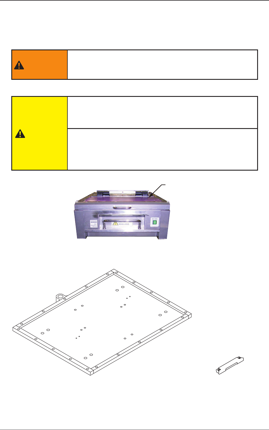
This unit consists of the single-transfer tray feeder (including xed pallet),
tray xing magnet and magnet attachment.
WARNING
Never modify the system to undo the interlock. It disables the
interlock function and might cause an injury.
CAUTION
When the cover is to be opened or closed, open or close it slowly
with the handle held securely.
Take care so that your nger is not caught.
When the cover is to be opened or closed, open or close it to the
end to obtain the damper effect. When the cover is not opened
or closed to the end, the damper effect is not obtained and
moreover, your hand or nger might be caught by the cover,
Cove
r
Fig. A3 Single Tray Feeder (Front Side of Machine)
Fixing Pallet (MP-G100)
Tray Fixing Magnet
(MF-G100)
Fig. A4 Fixing Pallet and Tray Fixing Magnet
1-13
Tg1576-ID-SO
0709-003
4.1 Single Tray Feeder
4.1 Single Tray Feeder
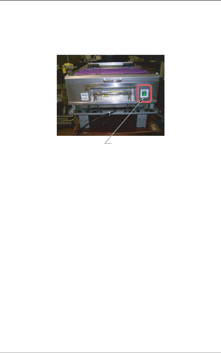
This mechanism is used for moving the pallet to the pick-up position.
This mechanism moves the pallet and transfers it to the component pick-
up position. Then, after the component pick-up, it houses the pallet at the
component replenishment position.
[TRAY READY] Switch
Fig. A5
[Traverse]
• This cylinder mechanism is used for transferring the pa
llet to the mponent
pick-up position. Using the cylinder forward and backward movement,
the pallet xed onto the cylinder is moved between the component pick-
up position (forward limit) and tray supply position (backward limit).
[TRAY READY]
• The tray supply door is opened or closed.
The LED shows the following conditions.
LED ON
: The door is locked.
LED OFF
: The door locking is cancelled.
1-14
Tg1576-ID-SO
4.2 Fixing Pallets
0711-003
4.2 Fixing Pallets
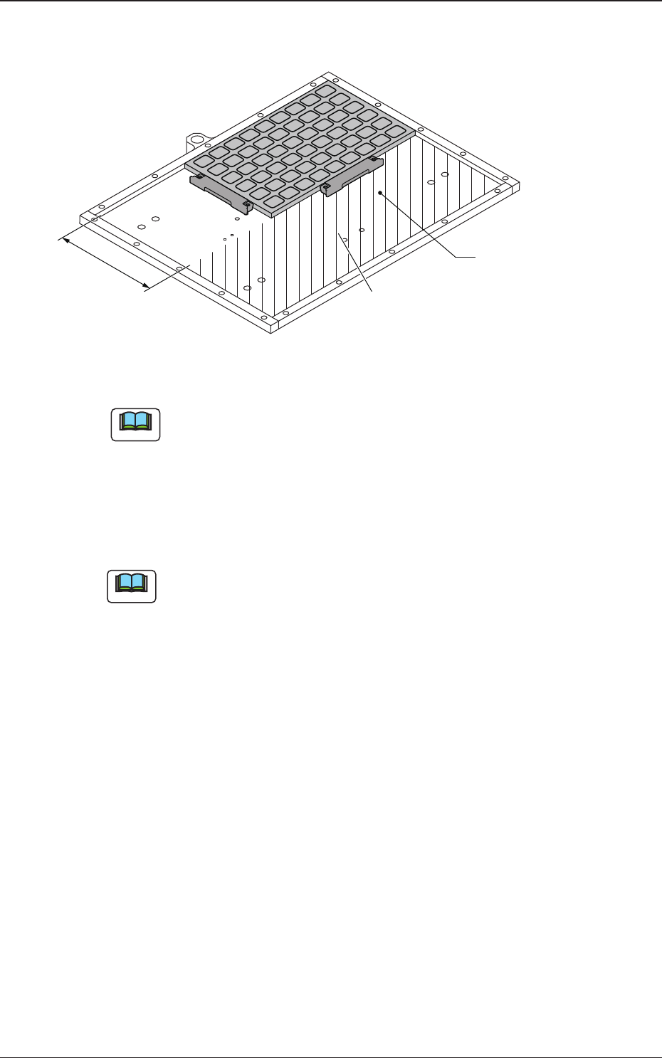
Fixing Pallet
Area where no tray should be put
136mm
Fig. A6 Fixing Pallet
Note
No tray should be put in the shadowed area.
•
Attachment of Tray
(1) Put the tray on the rear right side of the xing pallet.
(2) Hold the tray securely with the tray magnets.
Note
(a) Note that the tray magnets must be attached differently, depending on
the type or the shape of a tray.
(b) When the total mass (tray + components) exceeds "500 g", add the
tray magnets in the drawout direction of the pallet according to the
total mass.
Ref.:
One tray magnet has the capability to hold the weight of
approximately 500 g.
(c) It is recommended that up to 4 trays should be mounted when more
than one tray must be used although it is described in the
specications that up to 9 types of trays can be mounted.
(3) Check how the trays are mounted.
Check for any positional deviation of a component, missing
components, incorrectly seated trays (trays seated aoat), and incorrect
location of the tray magnets.
•
Detachment of Tray
(1) Detach the tray magnets.
(2)
Detach the tray from the xing pallet.