OM-1455-004_w.pdf - 第57页
2-8 Tg1576-ID-SO 2.2.3 Single-transfer T ray Feeder Component Replenishment Procedure (1) When the component shortage occurs, the “Component Replenishment” window is displayed and the supporting light is turned on. (2) P…
2-7
Tg1576-ID-SO
2.2.2 Tray Component Data
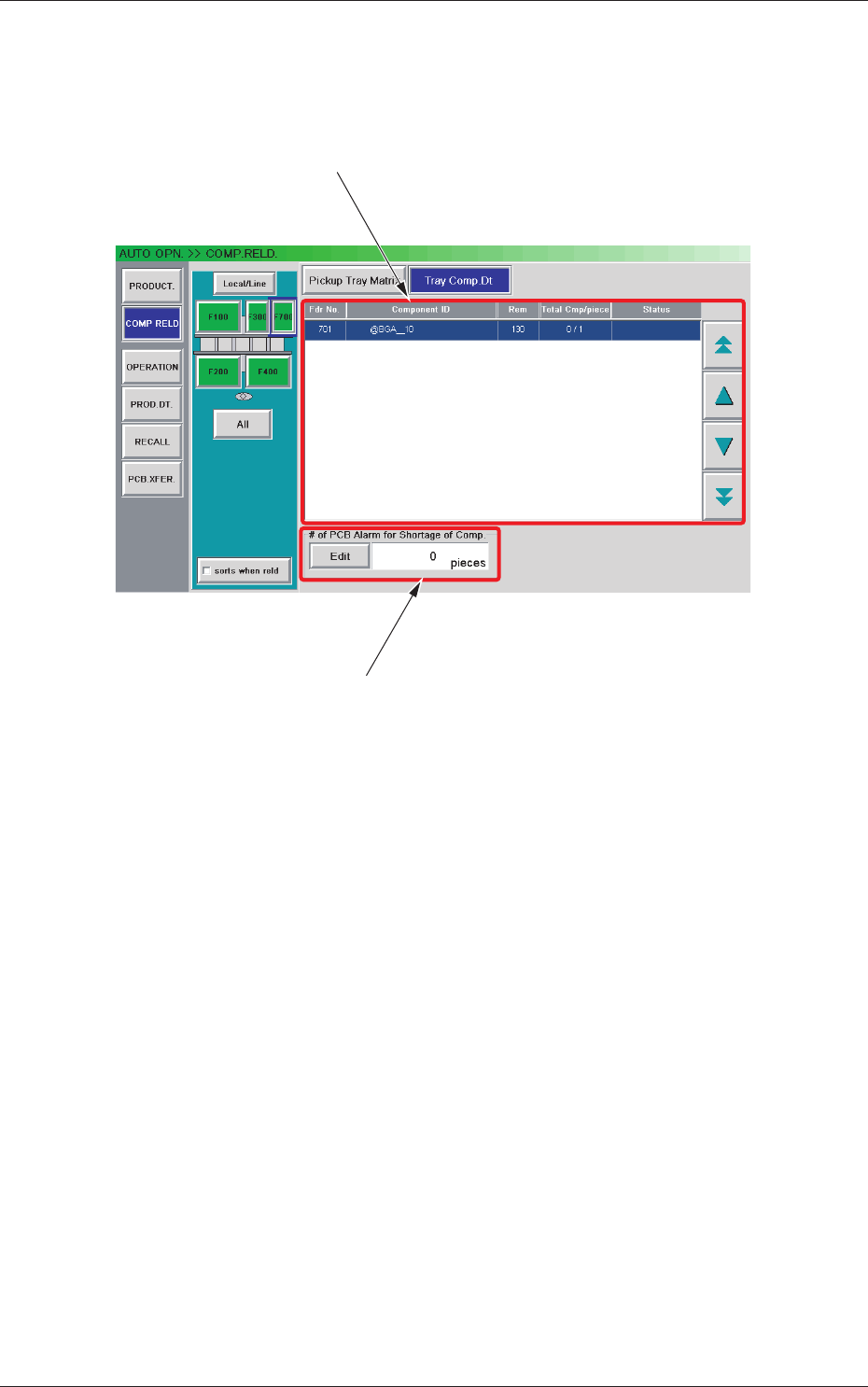
When the [Tray Comp. Dt] button is pressed in the "COMP. RELD."
window, the "Tray Comp. Dt" window appears.
[1]
[2]
Fig. B5 "Tray Comp. Dt" Window
[1] Information Display
Shown is the tray component data.
[2] "# of PCB Alarm for Shortage of Comp." Group Box
Set the number of PCBs to issue a component shortage alarm.
The [Edit] button can be used to set an arbitrary number of PCBs.
0707-001
2.2 Component Reloading

2-8
Tg1576-ID-SO
2.2.3 Single-transfer Tray Feeder Component Replenishment
Procedure
(1) When the component shortage occurs, the “Component
Replenishment” window is displayed and the supporting light is
turned on.
(2) Press the [Alm Release] button to cancel the alarm.
(3) The pallet xed onto the cylinder is automatically moved to the
component replenishment position and the cover lock for the
single-transfer tray is cancelled.
(4) The tray is replaced with a new tray
.
(5) Close the cover for the single-transfer tray and press the [TRAY
READY] button.
(6) The single-transfer tray cover will be locked and the
xed pallet
is moved to the component pick-up position.
(7) Set the replenished component quantity in the “Com
ponent
Replenishment” window.
2.2.4 Tape Feeder Component Replenishment
The procedure is the same as that for the usual component replenishment.
Note
In the case that the component shortage does not occur on the single-
transfer tray side, even when the feeder ready is cancelled, the xed
pallet for the single-transfer tray will not be returned to the component
replenishment position.
Reference
Refer to “2. Component Replenishment in Chapter 2 in Volume 1” in the
GXH series Instruction Manual for the component replenishment for the
tape feeder.
2.2 Component Reloading
0708-002
2-9
Tg1576-ID-SO
2.3 Operation
2.3.1 Test Mode
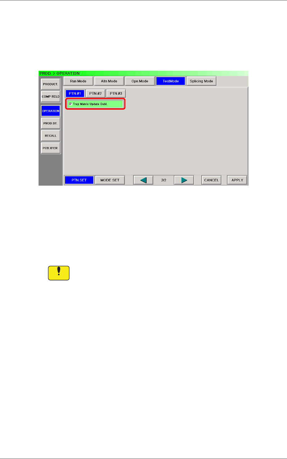
The corresponding window makes it possible to set parameters for the test
mode.
Fig. B6 "Test Mode" Window
Test Patterns
Set the contents of the test mode.
The following shows the items related to the single tray feeder.
Tray Matrix Update Dsbl.
Notice
Wrong selections (test run in wrong modes) will cause various
deciencies such as component picks by vacuum nozzles,
scattering of components, or collision with the chute, etc.
0708-002
2.3 Operation