OM-1455-004_w.pdf - 第77页
3-12 Tg1576-ID-SO (C03) T ray Step Data Fig. C10 "T ray Step" Edit Window (C03_01) Step Shown are the step Nos. of the magazine. The step Nos. have a button function. When one of these buttons is pressed, the c…

3-11
Tg1576-ID-SO
(C02_02) Component ID
Set component IDs in the text boxes.
(C02_03) C
Set control commands in the text boxes.
Notice
If a control command other than the following ones is used, the step
becomes invalid.
- (hyphen) :
This command handles the steps as those for the
placement feeder location data.
E :
This command shows the end of the placement feeder
location data.
The step where "E" is set is valid.
S :
This command invalidates the steps specied as
placement feeder location data.
X :
This command invalidates the steps specied as
placement feeder location data and shows the end of the
data.
(C02_05) Component Library Comment
Displayed are the comments entered in the component library data.
(C02_06) Dir [deg], Carrier Type
Displayed is the data specied in the component library data.
(C02_07) Used Parts
Displayed is the number of components to be used for one unit PCB.
(C02_08) Nozzle Type
Shown is the nozzle to be used, which is designated in the Handling/
Placement Data after the optimization operation.
0711-003
2.1 Description of Pattern Program
3-12
Tg1576-ID-SO
(C03) Tray Step Data
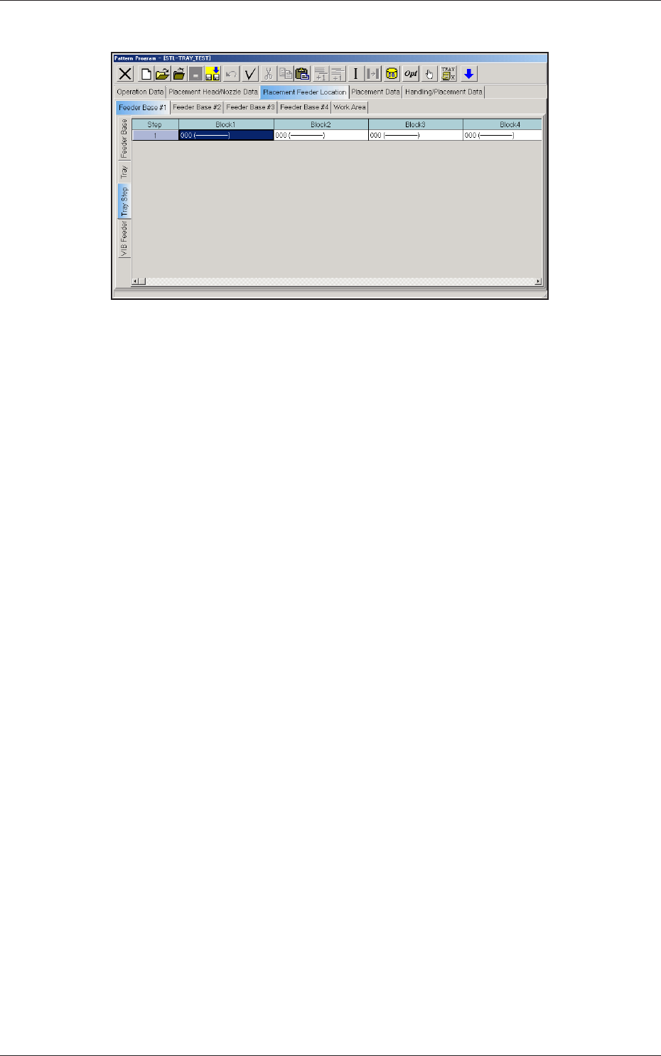
Fig. C10 "Tray Step" Edit Window
(C03_01) Step
Shown are the step Nos. of the magazine.
The step Nos. have a button function. When one of these buttons is
pressed, the corresponding "Tray Step Information" window opens.
(C03_02) Block 1 through 9
Specify where in each step and block various components specied in
the tray data should be arranged.
0711-002
2.1 Description of Pattern Program
3-13
Tg1576-ID-SO
2.1.2 Editing of Tray Step Information
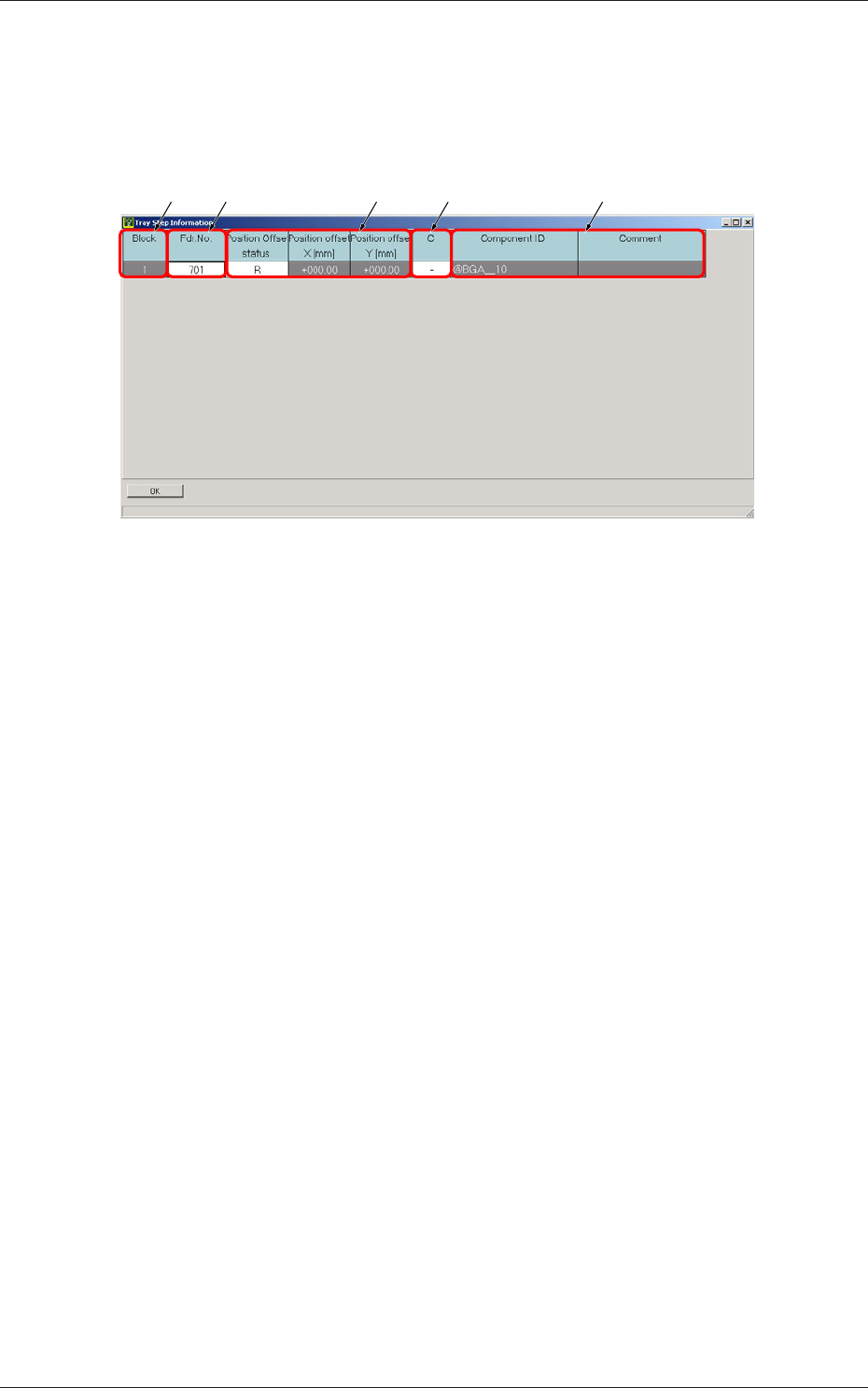
When a step No. is selected in the "Tray Step" edit window (Fig. C5-1), the
"Tray Step Information" window appears, enabling the operator to edit the
tray step information.
[1] [2] [4][3] [5]
Fig. C11 "Tray Step Information [1-15 Step]" Window
[1] Block
Shown are the block Nos.
[2] Fdr. No.
Displayed are the Nos. of the feeders arranged in each block.
[3] Position Offset status
Select "R", "L", or "Free Position" as Reference Point X for the block.
Position offset X [mm], Y [mm]
Enter the reference coordinates of the tray viewed from the pallet
reference position of each block.
[4] C
The control commands can be selected.
[5] Component ID and Comment
Displayed are the component IDs entered in the "Tray" edit window and
the comments entered in the component library data.
0711-002
2.1 Description of Pattern Program