OM-1455-004_w.pdf - 第81页
3-16 Tg1576-ID-SO 4.2 Auto Operation 4.2.1 T ray matrix update setup When the "T ray Matrix Update Setup" subtab is pressed in the "Auto Operation" tab sheet, the following subtab sheet appears. Fig. …
3-15
Tg1576-ID-SO
4. System Setting
4.1 Offset Data
4.1.1 Unit Offset
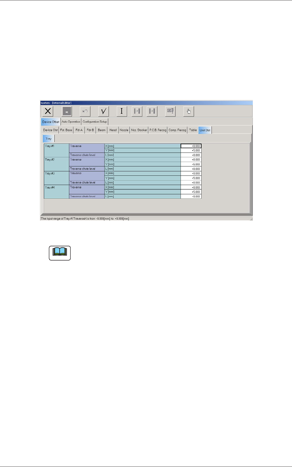
When the "Unit Ofst" subtab is pressed in the "Device Offset" tab sheet and
the "Tray" subtab is further pressed, the following subtab sheet appears.
Fig. C13 "Tray" Subtab Sheet
Note
The displayed subtab sheet will look different, depending on which option
is selected.
(1) Traverse
This offset is used to adjust the pallet drawing position.
X [mm] (Horizontal)
The set parameter is added to the beam travel when components are
picked up.
Y [mm] (Vertical)
The set parameter is added to the beam travel when components are
picked up.
(2) Traverse chute level
L [mm] (Height)
This offset data is used to adjust the level (height) of the pallet drawing
chute.
When a level lower than the design height is set, a plus value must be
entered in the text box.
0711-001
4. System Setting
3-16
Tg1576-ID-SO
4.2 Auto Operation
4.2.1 Tray matrix update setup
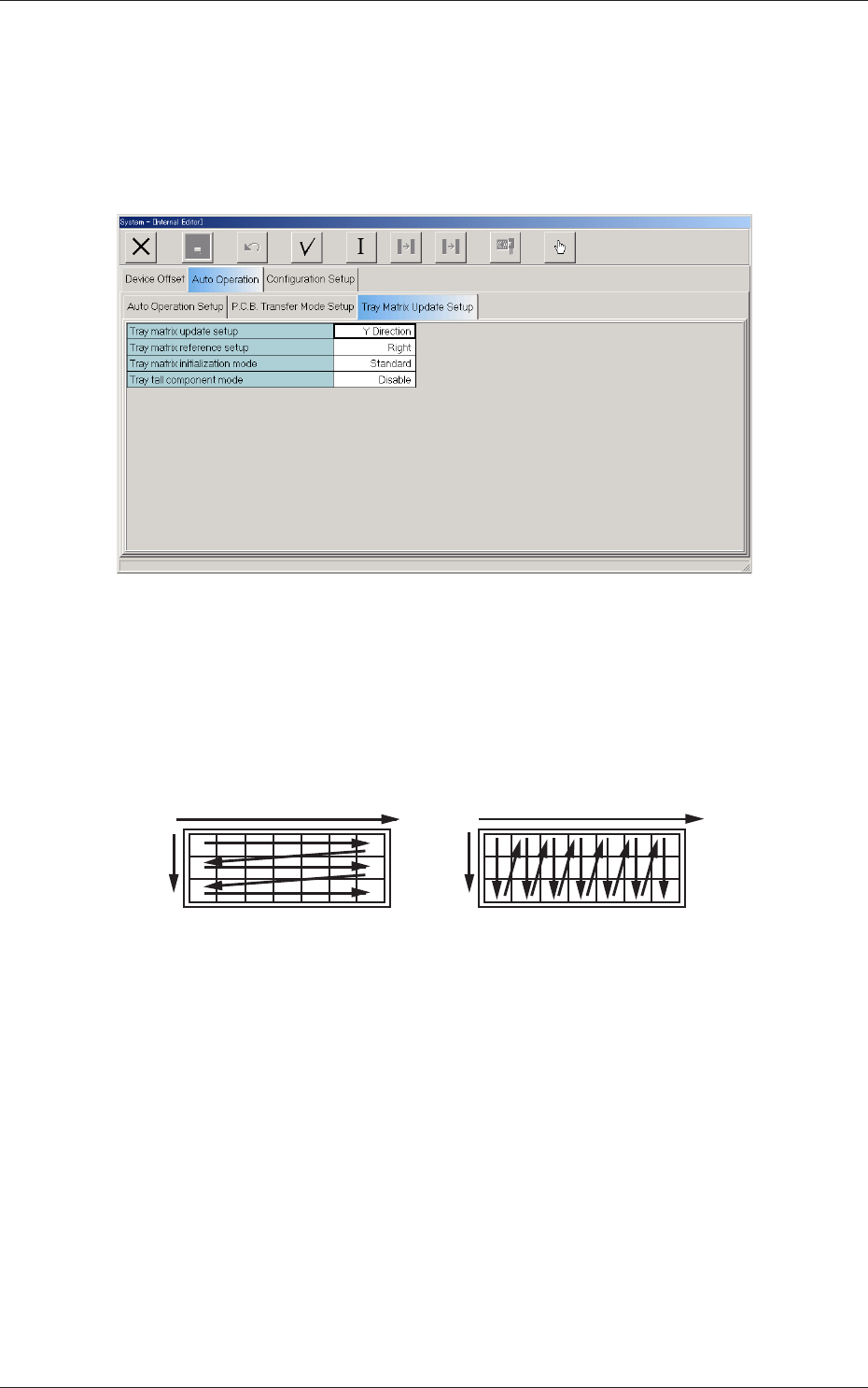
When the "Tray Matrix Update Setup" subtab is pressed in the "Auto
Operation" tab sheet, the following subtab sheet appears.
Fig. C14 "Tray Matrix Update Setup" Subtab Sheet
(1) Tray matrix update setup
Select "X Direction" or "Y Direction" (direction in which components
should be taken out) in the text box.
In normal cases, "Y Direction" should be selected.
X
Y
Y
Selection of "Y Direction"
Selection of "X Direction"
X
Fig. C15
0711-001
4.2 Auto Operation
3-17
Tg1576-ID-SO
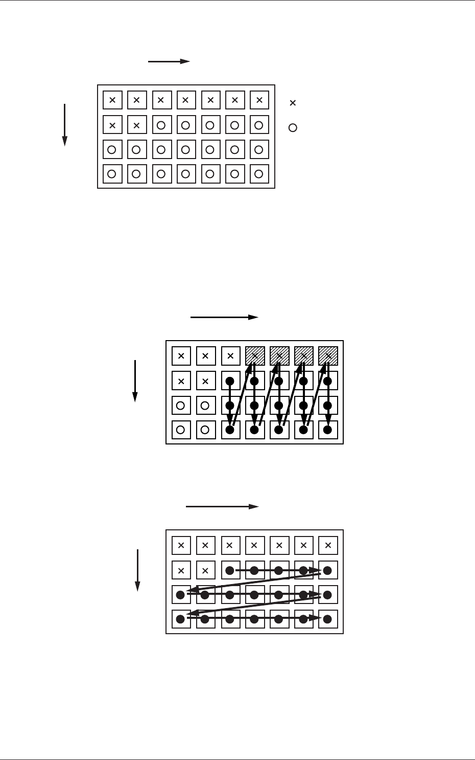
For example :
The tray is in the condition as shown in Fig. C11.
(Tray in Middle of Process)
1
1
2
99
2 3 99
X
Y
: No Component
(Taken Out)
: Component Existing
.
.
.
. . . . . .
Fig. C16
• The rst component pick-up position is assumed to be "X: 3, Y: 2".
: Component Picked Normally
: Component Left Behind
Shadowed : Mispick
1
1
2
99
2 3 99
X
Y
.
.
.
. . . . . .
Selection of "Y Direction"
Fig. C17
1
1
2
99
2 3 99
X
Y
.
.
.
. . . . . .
Selection of "Y Direction"
Fig. C18
0711-001
4.2 Auto Operation