QP341 351E规格书.pdf - 第13页
5.3 Nozzle Station (Optional) The following table details the available nozzle station selection. Notes: Nozzle station type B is used if the two-camera system is used at the rear of the machine. The capacity data may be…
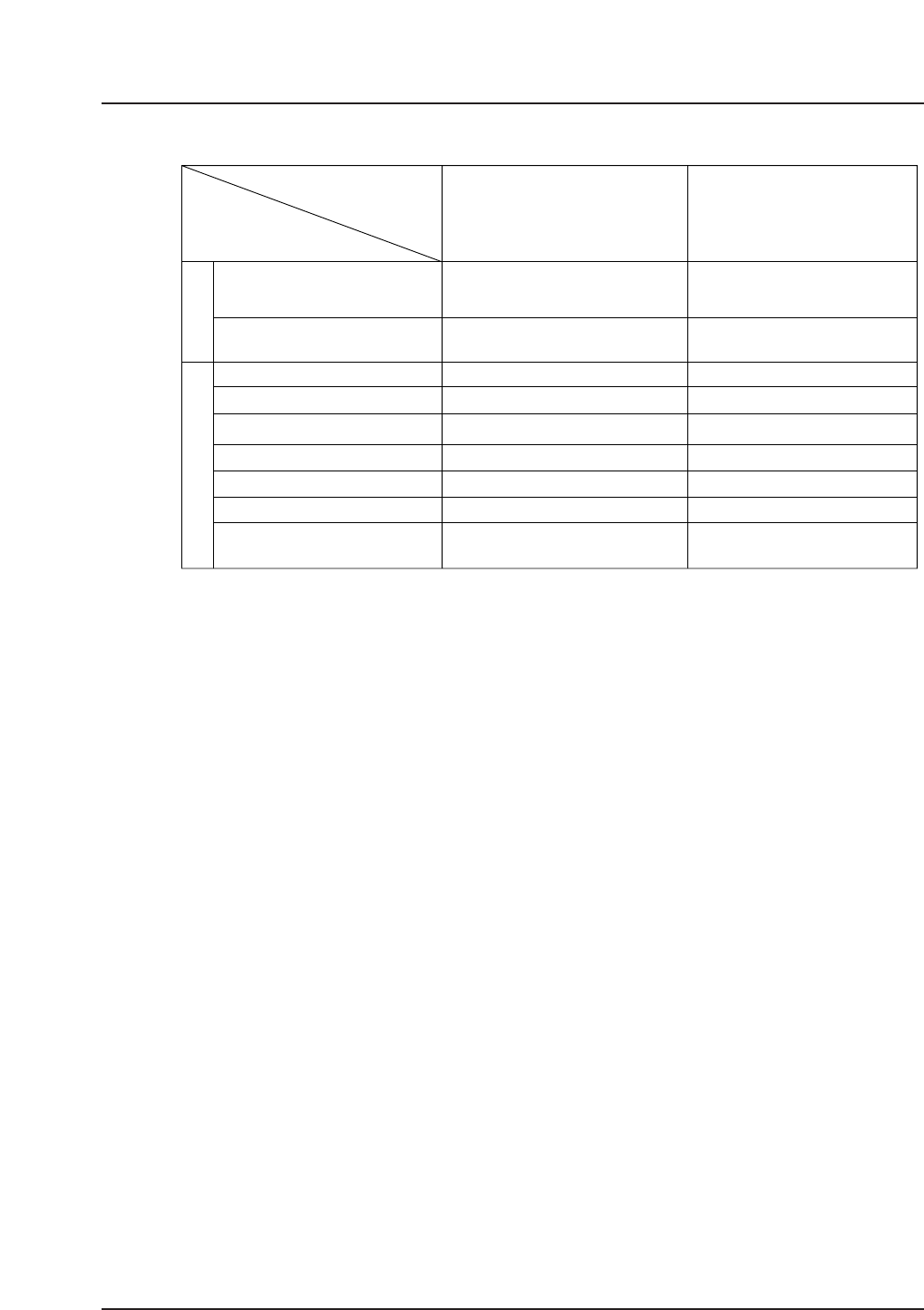
5.2 Camera Type Combinations
The above placing accuracy is achieved under Fuji’s specific conditions using a glass
board, glass parts, and PAM program.
(#1) Placing accuracy may vary depending on the camera and parts types. Placing accuracy for
parts with leads on all four sides is ±0.03 mm (3
σ
).
(#2) Special nozzles are available for parts of height between 10 and 25.4 mm.
(#3) To increase the range of parts that can be handled, an additional part inspection camera can
be attached at one or both sides of the machine.
1) Camera combinationLine-scan + CCD
2) Limitation (Rear side) Nozzle station B type only
(#4) 100 % detection of missing bumps on CSPs and BGAs.
Inspection results for CCGAs may be poor depending on the shape and detected light
reflected from the pins (cylinders).
CCGAs 1 x 1 mm to 50 x 74 mm can be handled. Testing is necessary for CCGAs of
42.5 x 42.5 mm and larger.
(#5) 100 % bump detection (except for white BGAs and CCGAs).
Orientation check for CSPs and BGAs.
Support for bump array parts from 1 x 1 mm to 55 x 74 mm.
(#6) Restrictions on part size may apply if parts are simultaneously picked up at all three
nozzles. Parts of up to 40 x 40 mm can be handled if the same part is picked up by all three
nozzles.
(#7) Supports the placement of parts with lengths of 74 mm to 150 mm.
The above specifications may be subject to change without notice.
Camera Type
Items
Placing accuracy (mm)
Max. placing height (mm)
Placing headVision system
Lighting
Camera type
Line-scan 2048
Min. lead pitch (mm)
Min. lead width (mm)
Part size (mm)
Min. space between leads (mm)
Adjustable frame function
Multiple image acquisition
or adjustable frame function
Line-Scan
3σ : ± 0.066 / ± 0.030
6σ : ± 0.132 / ± 0.060
CCD
10 (25.4)
Foreground and background
1608 (in. 0603) – 74 x 74 mm
0.24
3σ : ± 0.066
6σ : ± 0.132
CCD
Background
0603 (in. 0201) – 3216
QP3S011
___
___
___
___
___
(#1)
(#2)
(#4)
(#6)
(#5)
(#7)
(#3)
0.14
0.14
– 9 – QP-341E-MM/QP-351-MM Specifications
Preliminary (January 10, 2000)
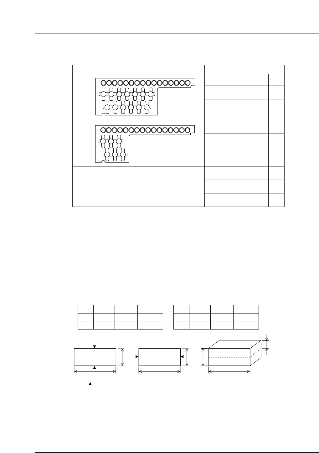
5.3 Nozzle Station (Optional)
The following table details the available nozzle station selection.
Notes: Nozzle station type B is used if the two-camera system is used at the rear of the machine.
The capacity data may be subject to changes in line with development.
Large mechanical chuck specifications are under development.
Two sizes of mechanical chuck are available; small (S), and large (L). As illustrated
below, both chuck types can be used to grasp parts at opposing points on either the
longest or shortest sides. The maximum part dimensions that can be handled by each
chuck type for each pick-up method are detailed in the tables below.
The vertical extent of the point on the side of the part at which the chuck makes contact
(t2 in the figure above) must be within the range of 1 to 8.5 mm. Mechanical chucks
which handle parts that exceed the dimensions shown above, may not be suitable for the
nozzle station. Contact Fuji for details of nozzle station modifications.
a
➀
➁
57
45
10
10
17
17
bt1
S type
(mm)
a
➀
➁
74
74
20
20
17
17
bt1
L type
(mm)
b
a
➀
b
t1
t2
a
➁
a
: Contact points
QP3S013
Type
Nozzle station shape
Capacity
Nozzles
Nozzles
Mechanical chucks S
Mechanical chucks L
Nozzles
Mechanical chucks S
Mechanical chucks L
Mechanical chucks S
Mechanical chucks L
16
13
0
16
6
0
–
–
–
Further models and designs pending.
Other
QP3S012
A: Single cameraB: Two-camera
system
Custom solutions available.
– 10 – QP-341E-MM/QP-351-MM Specifications
Preliminary (January 10, 2000)
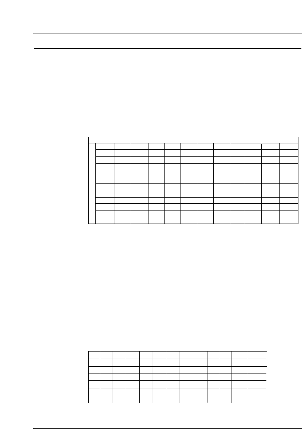
6. Parts Supply Units
6.1 Supply Units
This section describes the supply units supported by the QP-341E.
6.1.1 Multi-Feeder Unit (MFU-6) (Optional)
Mechanical IP-series and QP-242E feeders are supported by this unit which can
be used to perform batch changeovers. The tape index lever on IPC-type feeders
must be changed prior to use.
Refer to section 5.1 for details of feeder capacities.
Feeder setting conditions
Notes: Left side and right side refers to the feeder slots when viewed from the rear of
the machine.
1P, 2P etc. in the table indicates the number of pitches taken up by each feeder.
The number of neighboring slots taken up by each feeder setting is indicated in
parentheses.
Add one to the number of feeder pitches (e.g., 2P + 1P = 3P) when a Motor
Feeder is being loaded under the following circumstances.
• An 8 mm Motor Feeder, or an 8 or 12 mm IPC or BFC is loaded on the left
side of a 12 mm Motor Feeder.
• A 44 mm BFC is loaded on the left side of a 16 mm Motor Feeder.
• A 32 mm BFC is loaded on the left side of a 32 mm Motor Feeder.
• A 32 mm IPC is loaded on the left side of a 32 mm Motor Feeder.
Device table end-slot setting conditions
D1
D2
D3
D22
D23
D24
W8 W12 W16 W24 W32 W44 W56
Type 1 Type 2
W72 W88
QP3S015
#1: 56mm IPC and BFC feeders can be set at device position 2 (D2),
however 56 mm Motor Feeders cannot.
✓
✕
✓
✓
✓
✓
✓
✓
✓
✓
✓
✓
✓
✓
✓
✓
✓
✕
✕
✓
✓
✓
✓
✕
✕
✓
✓
✓
✓
✕
✕
✓
✓
✓
✓
✕
✕
✓ / ✕ (#1)
✓
✓
✓
✕
✕
✕
✓
✓
✕
✕
✕
✕
✕
✕
✕
✕
✕
✓
✓
✓
✓
✕
✕
✓
✓
✓
✓
✕
W8
W12
W16
W24
W32
W44
W56
1P(0)
1P(0)
2P(1)
2P(1)
2P(1)
2P(1)
3P(2)
3P (2)
4P (3)
1P(0)
1P(0)
2P(1)
2P(1)
2P(1)
2P(1)
3P(2)
3P (2)
4P (3)
2P(1)
2P(1)
2P(1)
2P(1)
2P(1)
3P(2)
3P(2)
4P (3)
4P (3)
2P(1)
2P(1)
2P(1)
2P(1)
2P(1)
3P(2)
3P(2)
4P (3)
4P (3)
2P(1)
2P(1)
2P(1)
3P(2)
3P(2)
3P(2)
4P(3)
4P (3)
4P (3)
2P(1)
2P(1)
3P(2)
3P(2)
3P(2)
3P(2)
4P(3)
4P (3)
5P (4)
Right side
Left side
W8 W12
2P(1)
2P(1)
2P(1)
2P(1)
2P(1)
2P(1)
3P(2)
4P (3)
4P (3)
W16 W24 W32 W44
3P(2)
3P(2)
3P(2)
3P(2)
3P(2)
4P(3)
4P(3)
4P (3)
5P (4)
3P(2)
3P(2)
4P(3)
4P(3)
4P (3)
4P(3)
4P(3)
5P (4)
5P (4)
4P(3)
4P (3)
4P(3)
4P(3)
4P(3)
4P(3)
4P(3)
4P(3)
5P(4)
5P(4)
6P(5)
4P(3)
5P (4)
W56
Type 1
2P(1)
2P(1)
2P(1)
2P(1)
2P(1)
3P(2)
3P(2)
4P (3)
4P (3)
Type 2
Type 1
Type 2
W72
W88
W72 W88
2P (1)
2P(1)
2P(1)
2P(1)
2P(1)
2P(1)
3P (2)
2P(1)
3P(2)
3P(2)
4P(3)
2P(1)
3P(2)
3P(2)
4P(3)
3P (2)
3P (2)
3P (2)
QP3S014
– 11 – QP-341E-MM/QP-351-MM Specifications
Preliminary (January 10, 2000)