QP341 351E规格书.pdf - 第15页
6.1.2 Power Feeder Unit (PFU) (Optional) NP-series and QP-132E Power Feeders are supported by this unit which can be used to perform batch changeovers. Refer to section 5.1 for details of unit holding capacities. 72 mm a…
6. Parts Supply Units
6.1 Supply Units
This section describes the supply units supported by the QP-341E.
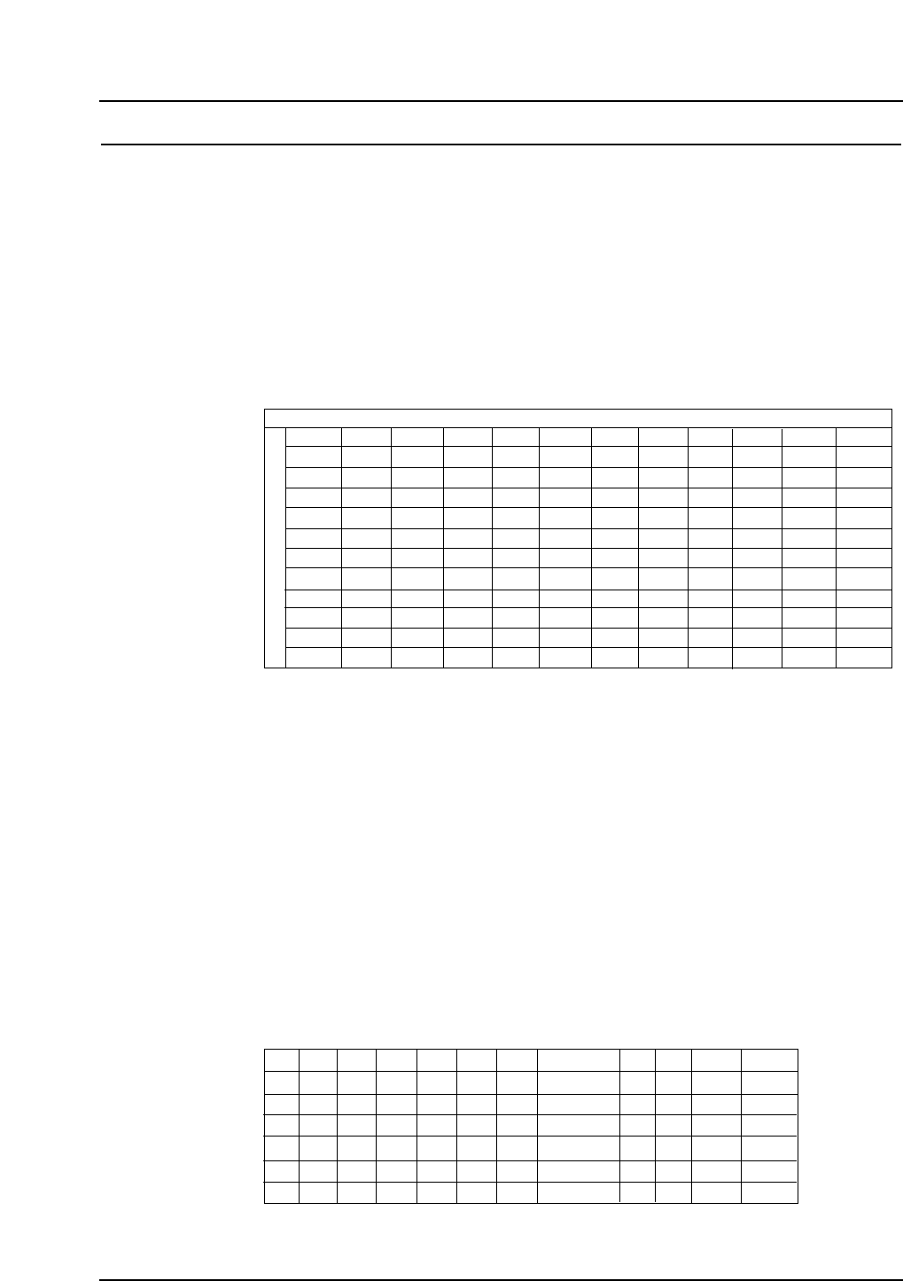
6.1.1 Multi-Feeder Unit (MFU-6) (Optional)
Mechanical IP-series and QP-242E feeders are supported by this unit which can
be used to perform batch changeovers. The tape index lever on IPC-type feeders
must be changed prior to use.
Refer to section 5.1 for details of feeder capacities.
Feeder setting conditions
Notes: Left side and right side refers to the feeder slots when viewed from the rear of
the machine.
1P, 2P etc. in the table indicates the number of pitches taken up by each feeder.
The number of neighboring slots taken up by each feeder setting is indicated in
parentheses.
Add one to the number of feeder pitches (e.g., 2P + 1P = 3P) when a Motor
Feeder is being loaded under the following circumstances.
• An 8 mm Motor Feeder, or an 8 or 12 mm IPC or BFC is loaded on the left
side of a 12 mm Motor Feeder.
• A 44 mm BFC is loaded on the left side of a 16 mm Motor Feeder.
• A 32 mm BFC is loaded on the left side of a 32 mm Motor Feeder.
• A 32 mm IPC is loaded on the left side of a 32 mm Motor Feeder.
Device table end-slot setting conditions
D1
D2
D3
D22
D23
D24
W8 W12 W16 W24 W32 W44 W56
Type 1 Type 2
W72 W88
QP3S015
#1: 56mm IPC and BFC feeders can be set at device position 2 (D2),
however 56 mm Motor Feeders cannot.
✓
✕
✓
✓
✓
✓
✓
✓
✓
✓
✓
✓
✓
✓
✓
✓
✓
✕
✕
✓
✓
✓
✓
✕
✕
✓
✓
✓
✓
✕
✕
✓
✓
✓
✓
✕
✕
✓ / ✕ (#1)
✓
✓
✓
✕
✕
✕
✓
✓
✕
✕
✕
✕
✕
✕
✕
✕
✕
✓
✓
✓
✓
✕
✕
✓
✓
✓
✓
✕
W8
W12
W16
W24
W32
W44
W56
1P(0)
1P(0)
2P(1)
2P(1)
2P(1)
2P(1)
3P(2)
3P (2)
4P (3)
1P(0)
1P(0)
2P(1)
2P(1)
2P(1)
2P(1)
3P(2)
3P (2)
4P (3)
2P(1)
2P(1)
2P(1)
2P(1)
2P(1)
3P(2)
3P(2)
4P (3)
4P (3)
2P(1)
2P(1)
2P(1)
2P(1)
2P(1)
3P(2)
3P(2)
4P (3)
4P (3)
2P(1)
2P(1)
2P(1)
3P(2)
3P(2)
3P(2)
4P(3)
4P (3)
4P (3)
2P(1)
2P(1)
3P(2)
3P(2)
3P(2)
3P(2)
4P(3)
4P (3)
5P (4)
Right side
Left side
W8 W12
2P(1)
2P(1)
2P(1)
2P(1)
2P(1)
2P(1)
3P(2)
4P (3)
4P (3)
W16 W24 W32 W44
3P(2)
3P(2)
3P(2)
3P(2)
3P(2)
4P(3)
4P(3)
4P (3)
5P (4)
3P(2)
3P(2)
4P(3)
4P(3)
4P (3)
4P(3)
4P(3)
5P (4)
5P (4)
4P(3)
4P (3)
4P(3)
4P(3)
4P(3)
4P(3)
4P(3)
4P(3)
5P(4)
5P(4)
6P(5)
4P(3)
5P (4)
W56
Type 1
2P(1)
2P(1)
2P(1)
2P(1)
2P(1)
3P(2)
3P(2)
4P (3)
4P (3)
Type 2
Type 1
Type 2
W72
W88
W72 W88
2P (1)
2P(1)
2P(1)
2P(1)
2P(1)
2P(1)
3P (2)
2P(1)
3P(2)
3P(2)
4P(3)
2P(1)
3P(2)
3P(2)
4P(3)
3P (2)
3P (2)
3P (2)
QP3S014
– 11 – QP-341E-MM/QP-351-MM Specifications
Preliminary (January 10, 2000)

6.1.2 Power Feeder Unit (PFU) (Optional)
NP-series and QP-132E Power Feeders are supported by this unit which can be
used to perform batch changeovers.
Refer to section 5.1 for details of unit holding capacities.
72 mm and wider Power Feeders, and stick feeders are under development.
Feeder setting conditions
Notes: Left side and right side refers to the feeder slots when viewed from the rear of
the machine.
1P, 2P etc. in the table indicates the number of pitches taken up by each feeder.
The number of neighboring slots taken up by each feeder setting is indicated in
parentheses.
Device table end-slot setting conditions
D1
D2
D23
D24
W8 W12 W16 W24 W32 W44 W56
Type 1 Type 2
–
–
–
–
W72 W88
–
–
–
–
–
–
–
–
–
–
–
–
QP3S017
✓
✓
✓
✓
✓
✓
✓
✓
✓
✓
✓
✓
✓
✓
✓
✕
✓
✓
✓
✕
✓
✓
✕
✕
✓
✓
✕
✕
W8
W12
W16
W24
W32
W44
W56
W72
W88
Type 1
Type 2
1P(0)
1P(0)
2P(1)
2P(1)
2P(1)
3P(2)
4P(3)
–
–
–
–
1P(0)
1P(0)
2P(1)
2P(1)
2P(1)
3P(2)
4P(3)
–
–
–
–
1P(0)
1P(0)
2P(1)
2P(1)
2P(1)
3P(2)
4P(3)
–
–
–
–
1P(0)
1P(0)
2P(1)
2P(1)
2P(1)
3P(2)
4P(3)
–
–
–
–
1P(0)
1P(0)
2P(1)
2P(1)
2P(1)
3P(2)
4P(3)
–
–
–
–
–
–
–
–
–
–
–
–
–
–
–
Right side
Left side
W8 W12
1P(0)
1P(0)
2P(1)
2P(1)
2P(1)
3P(2)
4P(3)
–
–
–
–
W16 W24 W32 W44
1P(0)
1P(0)
2P(1)
2P(1)
2P(1)
3P(2)
4P(3)
–
–
–
–
W56
–
–
–
–
–
–
–
–
W72
–
–
–
–
–
–
–
–
W88
Type 1
–
–
–
–
–
–
–
–
–
–
–
Type 2
QP3S016
–
–
–
–
–
–
– 12 – QP-341E-MM/QP-351-MM Specifications
Preliminary (January 10, 2000)
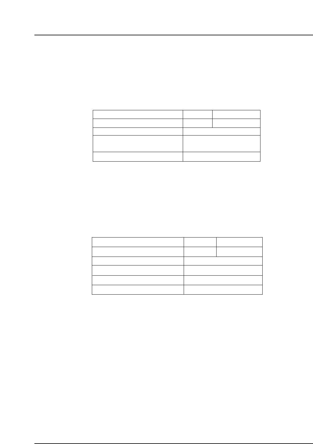
6.1.3 Multi-Tray Unit (MTU-8E and MTU-9E) (Optional)
Two models of MTU are available to supply parts from trays. The MTU-8E, in
which trays are positioned in the 50 available shelves in the magazine, and the
MTU-9E in which up to 8 trays can be stacked in each of ten extractable drawers.
A reject parts conveyor will be fitted to one side of the MTU-8E/9E, which can
handle parts up to 74 x 74 mm with heights of up to 25.4 mm.
• Up to 100 different part types can be supplied by loading two trays side by
side on each shelf.
• Trays with a total width (including part height) of 7.8 mm or more can be
handled by removing the shelf directly above.
• Up to 20 different part types can be supplied by loading two stacks of
smaller trays onto each shelf.
Tray size (mm)
Parts variation
Pitch (mm)
Tray height (mm)
Max. loading weight per shelf (kg)
335 x 330
10 types
160 x 330
20 types
32
4 – 32
Max. 240
Max. 4.0
MTU-9E
Weight of empty trays (g)
QP3S019
Tray size (mm)
Parts variation (50 levels)
Pitch (mm)
Tray height (mm)
Max. loading weight per shelf (g)
335 x 330
50 types
160 x 330
100 types
10
4 – 25
Max. 400
MTU-8E
QP3S018
Max. 7.8 at a pitch of 10 mm
– 13 – QP-341E-MM/QP-351-MM Specifications
Preliminary (January 10, 2000)