QP341 351E规格书.pdf - 第20页
6.1.13 Lead Coplanarity Check (Optional) (Under Development) • A laser lead locator (LLL) is used to scan the leads of a part to ensure none are bent up or down. • Compliant with JEDEC specifications. • Supported parts: …
6.1.8 Automatic Tape Cutter (Optional)
The automatic tape cutter is attached to an MFU-6E/PFU-3E or the fixed supply
side of the machine, and is used to cut off the waste tape when it reaches a given
length. If the tape cutter is attached to the fixed supply side, it must be installed
when the machine is built.
6.1.9 Tray Removal Confirmation (MTU-9E) (Optional)
A sensor is used to detect the presence of empty trays. This function is used to
prevent a wrongly removed tray from causing damage to the machine.
6.1.10 Area Sensor (Optional)
An area sensor is used to increase the safety of the MTU-8E/9E during automatic
operation.
6.1.11 Side Covers (Optional)
The covers available are detailed in the table below.
6.1.12 Smoke Colored Acryl Covers (Optional)
The brown acryl covers on the doors and fences can be replaced by smoke
colored covers.
B
C
D
E
F
Fixed type
Sliding-door type
Sliding-door type
(with safety switch)
Sliding-door type (partitioning)
Cannot be removed in multiunit setup.
Can be opened for easy maintenance in multiunit setup.
Can be opened without removal of screws to enable
easy maintenance on machines equipped with MTUs.
Same as C, but transparent. Attached to left side in
multiunit setup.
No cover fitted Can only be specified for the right side in multiunit setup.
Cover type DescriptionCode
Stand-alone or multiunit
Multiunit C, E
B, C, D
B, C, D
Left side Right sideSetup
F
Side cover configurations are shown in the table below.
QP3S044
– 16 – QP-341E-MM/QP-351-MM Specifications
Preliminary (January 10, 2000)

6.1.13 Lead Coplanarity Check (Optional) (Under Development)
• A laser lead locator (LLL) is used to scan the leads of a part to ensure none
are bent up or down.
• Compliant with JEDEC specifications.
• Supported parts:
• Parts with leads on all four sides (QFPs, VQFPs)
• Parts with leads on two sides (SOICs, VSOPs, TSOPs)
To enable use of the coplanarity check, the distance between the edge
of the nozzle (when holding a part) to the tip of the leads must be at
least 3 mm.
• Accuracy: ±0.01 mm
• Specifiable tolerance range: 20 – 3000 µm
• Measurement time (208 leads): Approx. 3.5 sec. /four sides
6.1.14 Placing Pressure Control (Optional) (Under Development)
The amount of pressure applied to parts when they are placed is controlled by
detecting the point at which the nozzle begins to apply pressure to the part, and
controlling the amount of down stroke from this position.
The amount of pressure for each part type is specified in part data.
Controllable pressure range: 120 gf – 1200 gf
Input units: 1 gf
Tolerance: ±20 g (for pressure of ≤ 250 gf)
±5 % (for pressure of > 250 gf)
Notes: Use of placing pressure control for flip chips and CSPs is under development.
Placing pressure control at less than 120 gf is under development.
6.1.15 Parts Confirmation Sensor (Optional) (Under Development)
A sensor is attached to the placing head to confirm that a part is being held by
the nozzle after pick up, and that the part is not present on the nozzle after
placement.
6.1.16 Insertion Control Placing (Pending) (Optional)
The torque limit of the motor is controlled to allow the insertion of parts such as
connectors. Pressure of up to 10 Kgf can be applied.
6.1.17 Vacuum Back-up Pins (Optional)
Four hollow pins with vacuum pads on top are used to support the board during
production.
– 17 – QP-341E-MM/QP-351-MM Specifications
Preliminary (January 10, 2000)
6.1.18 Rear Operation Panel (Optional)
For ease of operation, an operation panel can also be attached at the rear of the
machine.
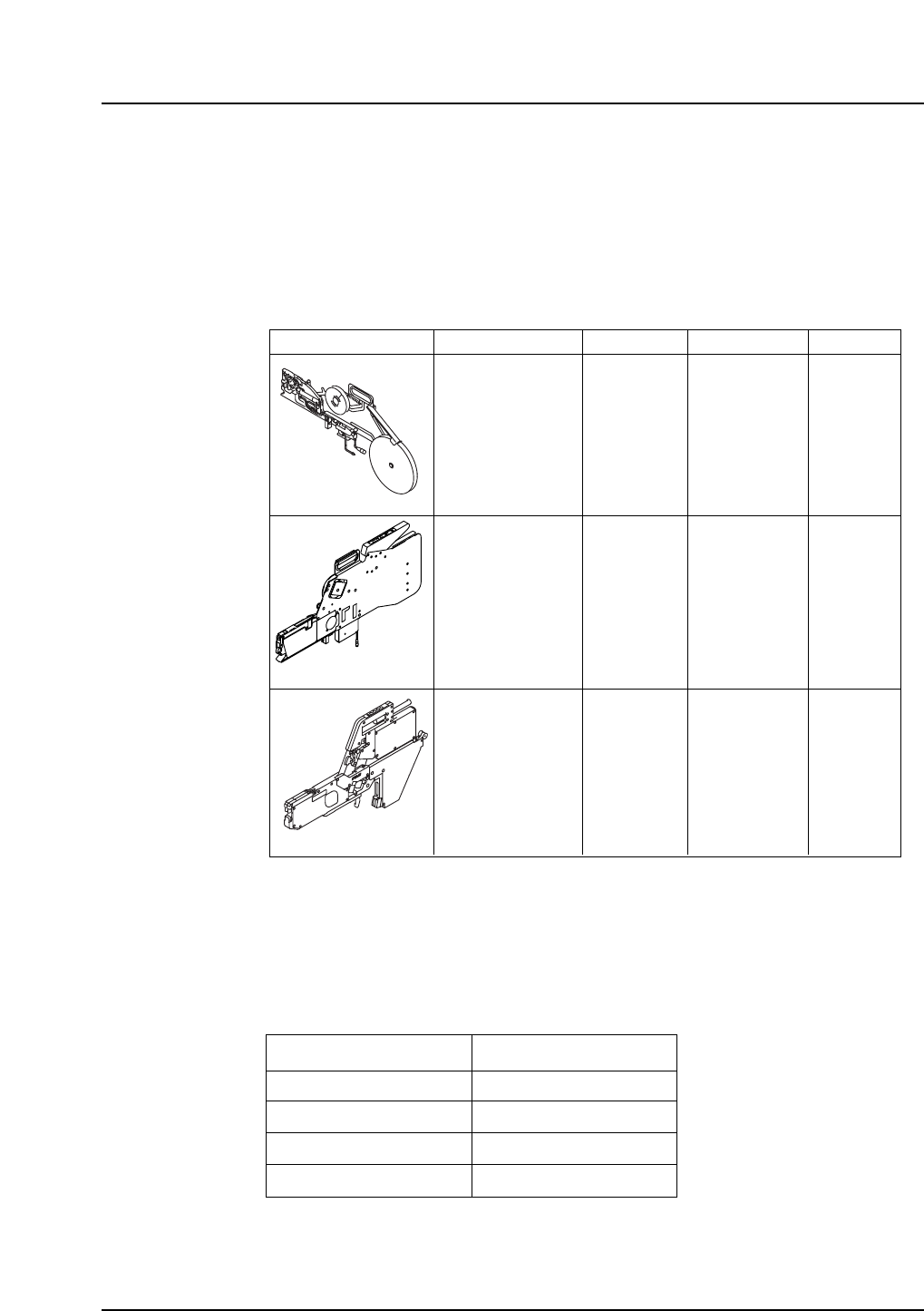
6.1.19 Mechanical Feeders (Optional)
8, 12, 16, 24, 32, 44, 56, 72, and 88 mm feeders available to handle all taping sizes.
• MFU-6E Feeders
Notes: The tape index lever on IPC feeders must be changed prior to use.
The feeding pitch for 12 mm and wider tape feeders can be adjusted in 4 mm
increments up to 60 mm using the dial on the feeder controls.
8 mm double channel feeder combinations are detailed in the table below.
Left
P4 paper
P4 embossed
P2 paper
P2 paper
P4 paper
P4 embossed
P2 paper
P4 paper
Right
QP3S046
Left and right facing the machine from the supply unit side.
Feeder type Tape width
8 – 56 mm MFU-6E
MFU-6E
PFU-3E
P4 x 1
P8 x 1
P12 x 1
P4 x n
P8 x n
P12 x n
Paper tape
Embossed tape
Paper tape
Embossed tape
P2 x 1
P4 x1
Variable
Embossed tape
P2 x 1
P4 x 1
Variable
(8 mm:
under development)
(12 - 72 mm,
88 mm special order)
Feeding pitch Tape type Feeder unit
BFC type
16 mm Motor Feeder
8 mm double channel feeder
QP3S025
8 – 24 mm
(32 – 56 mm:
under development)
(72, 88 mm
pending)
– 18 – QP-341E-MM/QP-351-MM Specifications
Preliminary (January 10, 2000)