QP341 351E规格书.pdf - 第6页
– 3 – QP-341E-MM/QP-351-MM Specifications Preliminary (January 10, 2000) 2.2 Machine Structure 2.2.1 Overview 2.2.2 Placing Head Nozzle 60 60 60 Background lighting QP3S002B (mm) Cameras Rear side PFU-3E MFU-6E MTU-8E/9E…
2. Machine Data and Structure
2.1 Machine Data and Operating Environment
Notes : Power Source: The built-in transformer has primary side taps of 200, 210, 220, 230, 380, 400,
415, 460 and 480 Volts.
A dedicated power source, not shared with other large equipment, should be used in order to
avoid problems with electrical noise, voltage fluctuations, high-frequency distortions, and other
related problems.
IP22: IEC compliant (protection against intrusion by body parts, solid objects and water).
QP3S001
Power & Air Requirements
Voltage:
Frequency:
Power consumption:
Air pressure:
Air consumption:
System Components
Display Panels
Color LCD touch panel
Language: Japanese or English
Weight
QP-341E:
MFU-6E (with tape cutter):
MTU-8E:
MTU-9E:
Installation Environment
Temperature:
Humidity:
Protective features: Class IP22 or equivalent
Color
50/60 Hz
2.5 kVA
200 V AC (± 10 %), three-phase
0.5 MPa (5 kgf/cm )
150 Nl/min.
1800 kg
Machine: Ivory
PCB conveyors
XY-robots
Part supply stations
Placing heads
Part and fiducial mark inspection cameras
30% to 80%
15°C to 35°C
2
+600 Nl/min. (empty tray rejection)
+55 Nl/min. (vacuum back-up)
QP-351E: 2050 kg
PFU-3E (with tape cutter):
180 kg
190 kg
360 kg
360 kg
– 2– QP-341E-MM/QP-351-MM Specifications
Preliminary (January 10, 2000)
– 3 – QP-341E-MM/QP-351-MM Specifications
Preliminary (January 10, 2000)
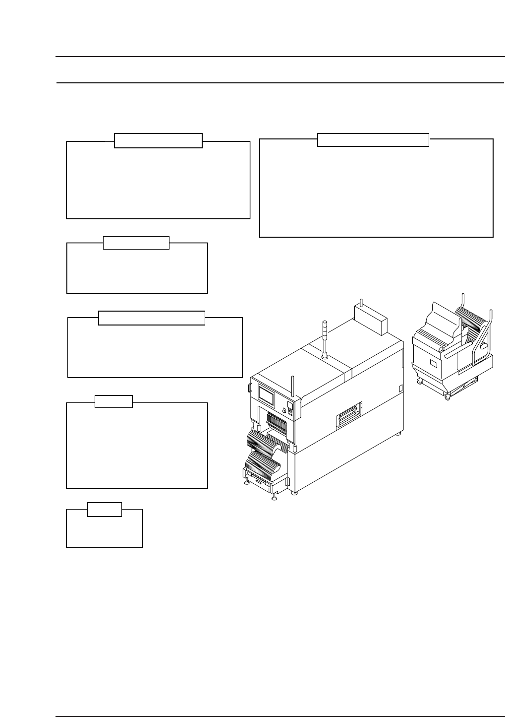
2.2 Machine Structure
2.2.1 Overview
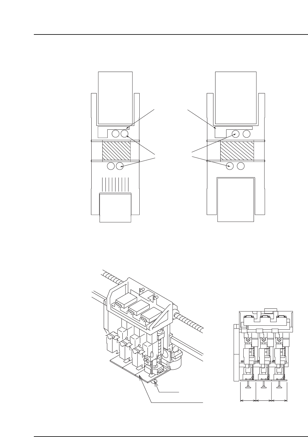
2.2.2 Placing Head
Nozzle
60 60 60
Background lighting
QP3S002B
(mm)
Cameras
Rear side
PFU-3E
MFU-6E
MTU-8E/9E
Front side (fixed)
QP3S002A
Nozzle
stations
MF, PF
or none
QP-341E
Rear side
PFU-3E
MFU-6E
MTU-8E/9E
Front side
QP-351E
MFU-6E
PFU-3E
or none
3. Machine Specifications
3.1 Performance Specifications
Items
Specifications
Placing accuracy
Fiducial mark
reading time
0.5 sec./mark
Obtained when reading a 1.2 mm diameter mark, excluding the time
required to travel from mark to mark and to make adjustments for mark
shape variations and location errors.
0.5 sec. / part Under Fuji specified conditions (Placing position, Part
type, PCB type, etc.)
Placing rate
Parts Part size: 0603 (in. 0201) – 74.0 x 74.0 mm (two-camera system)
Max.10 mm (foreground lighting)
Packaging EIA / EIAJ compliant tapes, sticks and trays
7 mm – 28 mm, 25 mm – 48 mm
Part inspection
CCD cameras or line-scan cameras
Compatible with both foreground and background
lighting
Tray:
160 x 330 mm, 335 x 330 mm
Placing reliability
99.99 % (including automatic recovery)
Errors due to packaging are not included.
Part height:
Lighting:
8, 12, 16, 24, 32, 44, 56, 72, and 88 mm
Stick:
Tape:
QP3S003
Notes: Parts of 74 mm x 74 mm or larger in size (up to 150 mm in
length) can be handled with use of adjustable frame vision
processing.
Restrictions on part size may apply if parts are simultaneously
picked up at all three nozzles.
Parts of 10 mm to 25.4 mm in height can be handled with
special nozzles.
Notes: Placing accuracy is obtained at Fuji using fiducial mark
referencing, and does not consider angular deviations.
Placing accuracy depends on the fabrication accuracy of the
PCB and the parts that are placed.
± 0.066 mm (3 σ)
± 0.132 mm (6 σ)
± 0.030 mm (3 σ)
± 0.060 mm (6 σ)
Rectangular chips and other small, odd-form parts
such as SOICs, PLCCs, BGAs, and CSPs
Medium to large size parts with leads on
all four sides.
QP-341E
QP-351E
Warranty period for this equipment is 6000 working hours or 2 years
(whichever elapses first).
Warranty period for the control software is 2000 working hours or 1 year
(whichever elapses first).
Fuji will bear no responsibility for damage due to acts of nature
(fire, flood, earthquakes, etc.) or incorrect operation.
Warranty period
Note: The placing rate may vary depending on the part
type, packaging, and tray positioning.
– 4 – QP-341E-MM/QP-351-MM Specifications
Preliminary (January 10, 2000)