QP341 351E规格书.pdf - 第8页
3.2 PCB Conveyance 3.3 PCBs Items Specifications Dimensions Thick. : 0.8 (0.5) mm to 4.0 mm Max. : 356 mm (W) x 457 mm (L) Min. : 50 mm (W) x 80 mm (L) Consult Fuji if the use of back-up pins is required for PCBs of 0.8 …
3. Machine Specifications
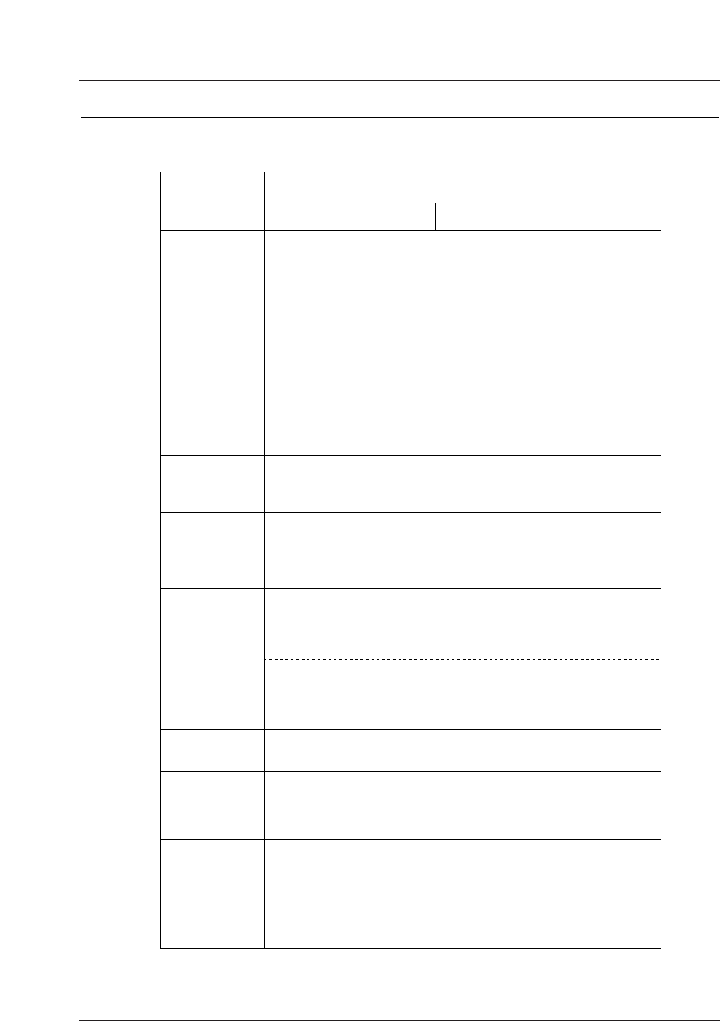
3.1 Performance Specifications
Items
Specifications
Placing accuracy
Fiducial mark
reading time
0.5 sec./mark
Obtained when reading a 1.2 mm diameter mark, excluding the time
required to travel from mark to mark and to make adjustments for mark
shape variations and location errors.
0.5 sec. / part Under Fuji specified conditions (Placing position, Part
type, PCB type, etc.)
Placing rate
Parts Part size: 0603 (in. 0201) – 74.0 x 74.0 mm (two-camera system)
Max.10 mm (foreground lighting)
Packaging EIA / EIAJ compliant tapes, sticks and trays
7 mm – 28 mm, 25 mm – 48 mm
Part inspection
CCD cameras or line-scan cameras
Compatible with both foreground and background
lighting
Tray:
160 x 330 mm, 335 x 330 mm
Placing reliability
99.99 % (including automatic recovery)
Errors due to packaging are not included.
Part height:
Lighting:
8, 12, 16, 24, 32, 44, 56, 72, and 88 mm
Stick:
Tape:
QP3S003
Notes: Parts of 74 mm x 74 mm or larger in size (up to 150 mm in
length) can be handled with use of adjustable frame vision
processing.
Restrictions on part size may apply if parts are simultaneously
picked up at all three nozzles.
Parts of 10 mm to 25.4 mm in height can be handled with
special nozzles.
Notes: Placing accuracy is obtained at Fuji using fiducial mark
referencing, and does not consider angular deviations.
Placing accuracy depends on the fabrication accuracy of the
PCB and the parts that are placed.
± 0.066 mm (3 σ)
± 0.132 mm (6 σ)
± 0.030 mm (3 σ)
± 0.060 mm (6 σ)
Rectangular chips and other small, odd-form parts
such as SOICs, PLCCs, BGAs, and CSPs
Medium to large size parts with leads on
all four sides.
QP-341E
QP-351E
Warranty period for this equipment is 6000 working hours or 2 years
(whichever elapses first).
Warranty period for the control software is 2000 working hours or 1 year
(whichever elapses first).
Fuji will bear no responsibility for damage due to acts of nature
(fire, flood, earthquakes, etc.) or incorrect operation.
Warranty period
Note: The placing rate may vary depending on the part
type, packaging, and tray positioning.
– 4 – QP-341E-MM/QP-351-MM Specifications
Preliminary (January 10, 2000)
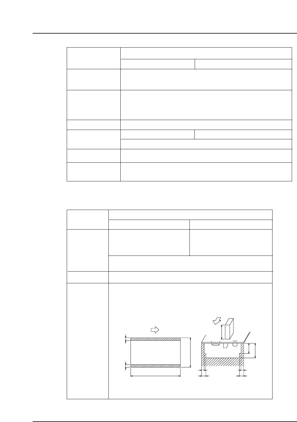
3.2 PCB Conveyance
3.3 PCBs
Items
Specifications
Dimensions
Thick. : 0.8 (0.5) mm to 4.0 mm
Max. : 356 mm (W) x 457 mm (L)
Min. : 50 mm (W) x 80 mm (L)
Consult Fuji if the use of back-up pins is required for PCBs of
0.8 mm or less in thickness.
Glass-epoxy, composite, paper phenol, ceramic, polyimide, etc. Material
3 3
19
25.4
55
33
MAX 25.4
L
W
PCB conditions
Warpage : Max. ± 1.0 mm
Premounted part height : Max. 25.4 mm
Premounted part height on lower surface : Max. 25.4 mm
(except for edge clearance for conveyor as shown below.)
(Units: mm)
QP3S005
QP-341E
QP-351E
Thick. : 0.8 (0.5) mm to 4.0 mm
Max. : 457 mm (W) x 508 mm (L)
Min. : 50 mm (W) x 80 mm (L)
The shaded area must be free of parts.
Items
Specifications
Flow direction
Conveyor height
Conveyor type
PCB loading time
PCB weight
Standard
Option
Standard
Option
Belt conveyor
4.2 sec.
PCB unloading → PCB loading → Clamping (PCB: 250 x 130 mm)
Up to 1 kg (Up to 2 kg when equipped with a roller conveyor)
Left to right
Right to left (specify when order is placed)
900 mm
950 mm
(specify when order is placed)
Conveyor width
Front rails are fixed; rear rails are adjusted using a handwheel.
QP3S004
adjustment
QP-341E
QP-351E
4.5 sec.
– 5 – QP-341E-MM/QP-351-MM Specifications
Preliminary (January 10, 2000)
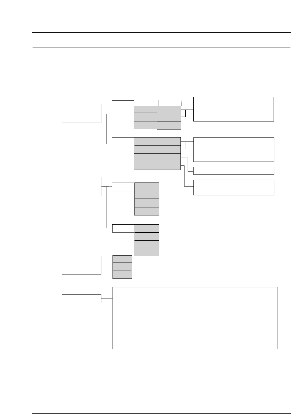
4. Machine Configuration
4.1 Machine Configuration Selection
Selection must be made of the type of feeder unit, parts recognition camera, and nozzle
station. Select one of the gray boxes within each group in the figure below.
QP3S006
Feeder Table
5.1
Front
MF
PF
None
A
B
Special
Rear
MFU-6E
PFU-3E
MTU-8E
MTU-9E
6.1.1
6.1.2
6.1.3
6.1.3
6.1.6
6.1.7
6.1.8
STU
Reject parts conveyor
Automatic tape cutter
6.1.10 Area sensor
6.1.9
6.1.10
Tray removal confirmation
Area sensor
Cameras
5.2
Nozzle station
5.3
Front
Rear
Nozzles
Special nozzles
and mechanical chucks
Side covers
Acryl covers (fence, door)
Lead coplanarity check
Placing pressure control
Parts confirmation sensor
Insertion control placing
Vacuum back-up pins
Rear operation panel
Mechanical feeders
Stick feeders
Feeder stand
Feeder set-up jig
Tape splicer
Roller conveyor
Handy Terminal
Kitting Station
HELPS
6.1.4
6.1.5
6.1.11
6.1.12
6.1.13
6.1.14
6.1.15
6.1.16
6.1.17
6.1.18
6.1.19
6.1.20
6.1.21
6.1.22
6.1.23
6.1.24
6.1.25
6.1.26
6.1.27
Other
Line-scan
CCD
LS + CCD
None
Line scan
CCD
LS + CCD
MF: IP-series, QP-242E feeders
PF: QP-132E, NP-series Power Feeders
Nozzle station type B is used if the two-camera system
is used at the rear of the machine.
Note: Refer to the associated section numbers for further details of each item.
Certain items in the list above may be under development or pending.
MFU-6E
PFU-3E
None
QP-341E
QP-351E
None
6.1.6
6.1.7
6.1.8
STU
Reject parts conveyor
Automatic tape cutter
– 6 – QP-341E-MM/QP-351-MM Specifications
Preliminary (January 10, 2000)