00192471-03.pdf - 第109页
User Manual SIPLAC E HS-50 3 What to do when ... Software Version SR.50x.xx 01/2006 US Edition 3.7 Changing the set-up 109 3 Fig. 3.7 - 1 Chang ing the component table 3 (1) B utton for rai sing and lowerin g the comp on…
3 What to do when ... User Manual SIPLACE HS-50
3.7 Changing the set-up Software Version SR.50x.xx 01/2006 US Edition
108
3.7.2 What you should note when changing the component table
Æ Set up the feeder modules in the external set-up area according to the changeover instruc-
tions. Follow the preliminary set-up instructions in section 3.6
.
3
WARNING
NEVER place your hand in one of the gaps between the component change table and the ma-
chine stand while the machine is running (see Fig. 3.7 - 1, No. 8). 3
WARNING
The power supply cable for the component table may only be plugged into or unplugged from the
socket on the placement station if the component table is correctly inserted in the set-up area of
the station. 3
WARNING
It is prohibited to plug the power supply cable for the component table in the socket on the place-
ment station to operate the component table when away from the station via the compressed air
controller. 3
3
User Manual SIPLACE HS-50 3 What to do when ...
Software Version SR.50x.xx 01/2006 US Edition 3.7 Changing the set-up
109
3
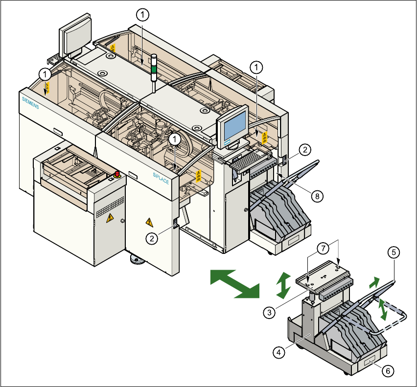
Fig. 3.7 - 1 Changing the component table
3
(1) Button for raising and lowering the component tabletop
(2) Socket for connecting the power supply cable
(3) Component tabletop (can be raised and lowered)
(4) Component table
(5) Bracket
(6) Tape waste container
(7) Centered bore hole for the centering pin
(8) Gap between the component table and machine stand
3
3 What to do when ... User Manual SIPLACE HS-50
3.7 Changing the set-up Software Version SR.50x.xx 01/2006 US Edition
110
3.7.2.1 Disconnecting the component table
3
Æ Click on the symbol (Stop processing PCB) in the main view of the station computer
user interface. The station will continue to place components until the current PCBs are com-
pletely populated and have been transported to the intermediate or output conveyor, i.e. until
the processing conveyors are empty.
Æ Click in the tool bar in the main view on the symbol for the gantry that you want to move out of
the feeder area using the gantry functions.
Æ Click in the "Gantry functions" view on the Move to set-up position button and press the start
key as often as you are requested to do so.
The gantry moves from the feeder area to the set-up position.
Æ Open the protective cover of the selected gantry.
Æ Push the bracket of the component table upwards (see Fig. 3.7 - 1, No. 5).
This places the raised component tabletop in its end position.
Æ Open the cover over the button used to raise and lower the component tabletop (see
Fig. 3.7 - 1
, No. 1).
Æ Press the button and hold it down until the component tabletop (see Fig. 3.7 - 1, No. 3) is in its
upper end position.
The component tabletop latches into the raised position when the button is released.
Æ Unplug the power supply cable of the component table from the socket on the station (see Fig.
3.7 - 1
, No. 2).
Æ Pull out the component table.