00192471-03.pdf - 第111页
User Manual SIPLAC E HS-50 3 What to do when ... Software Vers ion SR.50x.xx 01/2006 US Edition 3.8 How to avoid track errors 111 3.8 How to avoid track er rors 3.8.1 General informat ion Æ Make sure tha t the area s aro…
3 What to do when ... User Manual SIPLACE HS-50
3.7 Changing the set-up Software Version SR.50x.xx 01/2006 US Edition
110
3.7.2.1 Disconnecting the component table
3
Æ Click on the symbol (Stop processing PCB) in the main view of the station computer
user interface. The station will continue to place components until the current PCBs are com-
pletely populated and have been transported to the intermediate or output conveyor, i.e. until
the processing conveyors are empty.
Æ Click in the tool bar in the main view on the symbol for the gantry that you want to move out of
the feeder area using the gantry functions.
Æ Click in the "Gantry functions" view on the Move to set-up position button and press the start
key as often as you are requested to do so.
The gantry moves from the feeder area to the set-up position.
Æ Open the protective cover of the selected gantry.
Æ Push the bracket of the component table upwards (see Fig. 3.7 - 1, No. 5).
This places the raised component tabletop in its end position.
Æ Open the cover over the button used to raise and lower the component tabletop (see
Fig. 3.7 - 1
, No. 1).
Æ Press the button and hold it down until the component tabletop (see Fig. 3.7 - 1, No. 3) is in its
upper end position.
The component tabletop latches into the raised position when the button is released.
Æ Unplug the power supply cable of the component table from the socket on the station (see Fig.
3.7 - 1
, No. 2).
Æ Pull out the component table.
User Manual SIPLACE HS-50 3 What to do when ...
Software Version SR.50x.xx 01/2006 US Edition 3.8 How to avoid track errors
111
3.8 How to avoid track errors
3.8.1 General information
Æ Make sure that the areas around the feeder modules are clean and that there are no loose
components in the feeder area or under the feeder modules.
Æ Ensure that the supporting surfaces of the feeder modules, and particularly the magnetic rails
of the component tables, are clean and level.
Æ Refill promptly with components.
Æ Splice the tapes promptly. This generally means that you are to prepare the splicing material
when there is still approximately 1.5 m of tape on the reel.
Æ Handle the feeder modules carefully when you insert them into or remove them from the com-
ponent table as these are high-precision devices.
Æ When you insert the feeder modules, make sure that you do not accidentally press one of the
program keys. If you do, you could change the advance from 4 mm to 2 mm on
8 mm S feeder modules, for example.
Æ Close the flaps of the feeder modules because they can be easily damaged when open.
Æ For 8 mm S feeder modules, make sure that the components are picked up from the correct
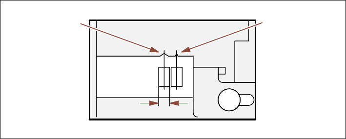
position, depending on their sizes (see the following example).
Example for 8mm S feeder modules 3
3
Fig. 3.8 - 1 Pick-up position for components (> 3 mm, </=
3 mm)
Æ Check to see if all the plugs of the feeder modules are plugged in to the correct sockets.
Pick-up position
Pick-up position
> 3 mm
for components
for components
Width
≤ 3 mm

3 What to do when ... User Manual SIPLACE HS-50
3.8 How to avoid track errors Software Version SR.50x.xx 01/2006 US Edition
112
3.8.2 ... on the 8 mm S tape feeder module
Æ NEVER open the cover flap without first releasing the tension of the cover foil remover.
Æ Set the pick-up position and the spacing of the tape according to the short instructions en-
closed with each tape feeder module.
Æ Insert the tape material over the spring into the tape feeder module.
3.8.3 ... on the tape container
Æ Insert the spacers correctly (see Fig. 3.5 - 2).
Æ Use insertable shafts for large tape reels.