00192471-03.pdf - 第137页
User Manual SIPLAC E HS-50 4 Component han dling Software Version SR.50x.xx 01/2006 US Edition 4.6 Component changeover tables 137 4 Fig. 4.6 - 2 Chang ing the component changeover table (1) B utton for rai sing and lowe…
4 Component handling User Manual SIPLACE HS-50
4.6 Component changeover tables Software Version SR.50x.xx 01/2006 US Edition
136
4.6.2 Undocking the component changeover table
Æ Click on the STOP PROCESSING icon in the MAIN VIEW menu.
Æ The PCB in progress will be completed. The icons of the SINGLE FUNCTIONS menu will then
be activated.
Æ Click on the SINGLE FUNCTIONS GANTRY X icon (gantry 1, 2, 3 or 4).
Æ Click on the GANTRY FUNCTIONS icon.
Æ From this menu, click on the APPROACH SET-UP POSITION button.
Æ The selected placement head will move across the PCB transport to prevent it being damaged
when the component table is changed.
Æ Fold up the protective cover of the selected gantry.
Æ Lift up the clip (item 5) to lock the raised component table bed in its top end position.
Æ Lift the flap over the button (item 1).
Æ Hold down the button (item 1) for raising the component table bed (item 3) until the component
table bed reaches its top end position.
Æ Unplug the component changeover table (item 2) from the placement system.
Æ Remove the component changeover table.
4
User Manual SIPLACE HS-50 4 Component handling
Software Version SR.50x.xx 01/2006 US Edition 4.6 Component changeover tables
137
4
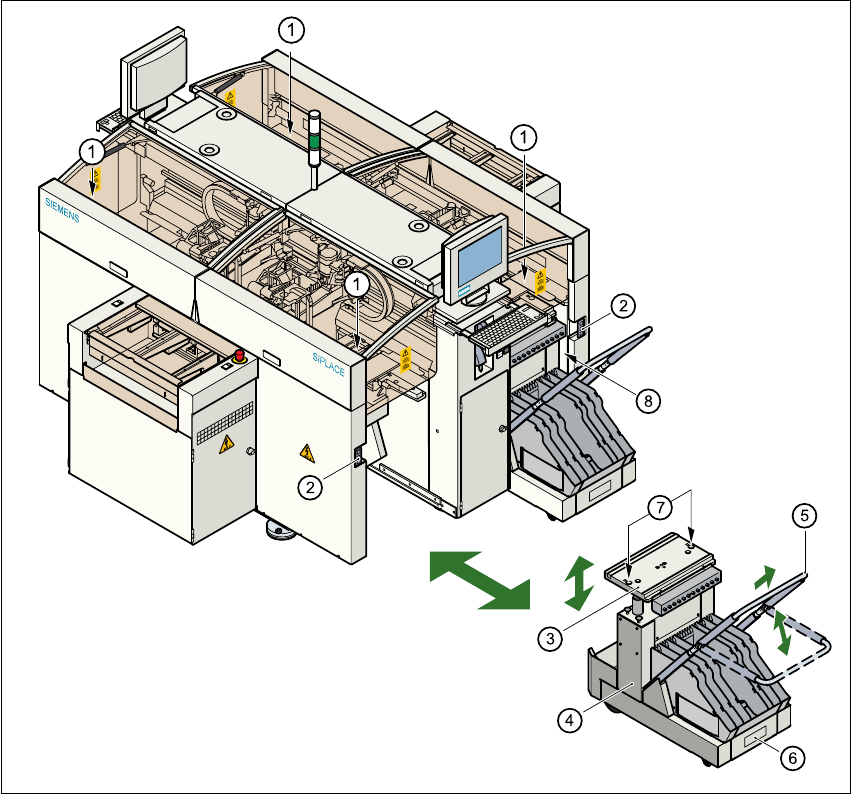
Fig. 4.6 - 2 Changing the component changeover table
(1) Button for raising and lowering the component table plate
(2) Plug for connecting the component changeover table cable
(3) Component table bed, can be raised and lowered
(4) Component changeover table
(5) Bracket
(6) Used tape container
(7) Centering holes for the centering pins
(8) Gap between the component table and machine stand
4 Component handling User Manual SIPLACE HS-50
4.6 Component changeover tables Software Version SR.50x.xx 01/2006 US Edition
138
4.6.3 Docking the component changeover table
WARNING 4
Check that the placement head is outside the range of the component changeover table.
CAUTION 4
When docking the component table, ensure that the table bed is in its top end position and the
clip (item 5) is folded up.
Æ Carefully push the component changeover table into the placement system.
Æ Plug the connecting cable for the component changeover table into the socket (item 2) in the
placement system.
Æ Open the flap over the push-button for raising the component changeover table.
Æ Hold down the button (item 1) until the component table bed reaches its top end position.
Æ Check that the centering holes in the component table bed are exactly over the centering pins
on the placement system.
Æ Then fold down the clip (item 5) of the component changeover table to lower the component
table bed.
Æ Ensure that the centering pins engage in the centering holes in the component table bed and
that the component table bed is fully lowered.
Æ Close the flap over the push-button (item 1).
Æ Close the protective cover.
4