00192471-03.pdf - 第138页
4 Component handling User Manual SIPLACE HS-50 4.6 Component c hangeover tables Software Version SR.50x.xx 01/ 2006 US Edition 138 4.6.3 Docking the compone nt changeover t a ble W ARNING 4 Check tha t the plac ement hea…
User Manual SIPLACE HS-50 4 Component handling
Software Version SR.50x.xx 01/2006 US Edition 4.6 Component changeover tables
137
4
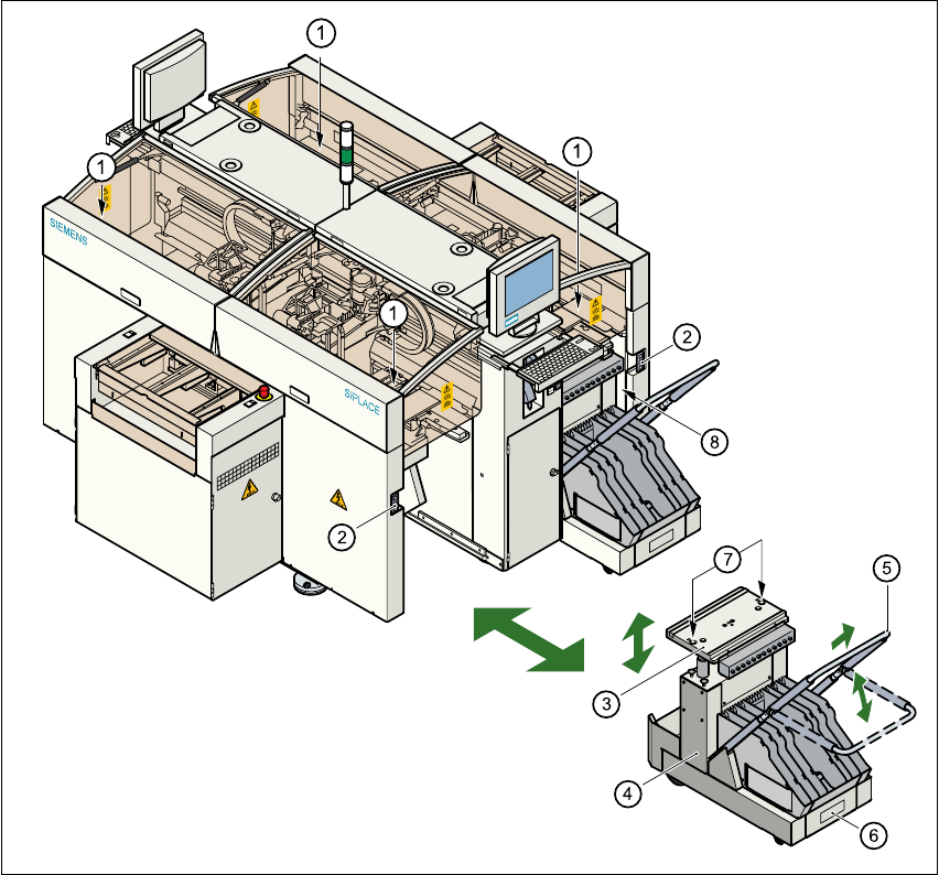
Fig. 4.6 - 2 Changing the component changeover table
(1) Button for raising and lowering the component table plate
(2) Plug for connecting the component changeover table cable
(3) Component table bed, can be raised and lowered
(4) Component changeover table
(5) Bracket
(6) Used tape container
(7) Centering holes for the centering pins
(8) Gap between the component table and machine stand
4 Component handling User Manual SIPLACE HS-50
4.6 Component changeover tables Software Version SR.50x.xx 01/2006 US Edition
138
4.6.3 Docking the component changeover table
WARNING 4
Check that the placement head is outside the range of the component changeover table.
CAUTION 4
When docking the component table, ensure that the table bed is in its top end position and the
clip (item 5) is folded up.
Æ Carefully push the component changeover table into the placement system.
Æ Plug the connecting cable for the component changeover table into the socket (item 2) in the
placement system.
Æ Open the flap over the push-button for raising the component changeover table.
Æ Hold down the button (item 1) until the component table bed reaches its top end position.
Æ Check that the centering holes in the component table bed are exactly over the centering pins
on the placement system.
Æ Then fold down the clip (item 5) of the component changeover table to lower the component
table bed.
Æ Ensure that the centering pins engage in the centering holes in the component table bed and
that the component table bed is fully lowered.
Æ Close the flap over the push-button (item 1).
Æ Close the protective cover.
4

User Manual SIPLACE HS-50 5 Station extensions
Software Version SR.50x.xx 01/2006 US Edition 5.1 Nozzle changer for the 12-segment collect&place head
139
5 Station extensions
5.1 Nozzle changer for the 12-segment collect&place
head
5.1.1 Overview
The placement system is supplied as standard with four collect&place heads and four nozzle
changers. As an option, a second nozzle changer can be installed for each collect&place head.
The nozzle changer consists of at least one, and up to five magazines, each with 12 nozzle ga-
rages (see Fig. 5.1 - 1
). The magazines are seated on a common support and each magazine is
centered using two parallel pins and fixed in place with clips.
5.1.2 Technical data
5
Nozzle changer for the 12-segment collect&place head
Dimensions (length x width x height) 472.5 mm x 64 mm x 90 mm
Number of nozzle garages Min. 12 / max. 60
Nozzle types 9xx
Time required to open and close the locking plate < 200 ms
Pneumatic circuit Air line 5.3 bar