00192471-03.pdf - 第139页
User Manual SIPLACE HS-50 5 Station extensions Software Version SR.50x.xx 01/2006 US Edition 5.1 Nozzle changer for the 12-segment collect&place head 139 5 S t ation extensions 5.1 Nozzl e chan ger for th e 12-seg me…
4 Component handling User Manual SIPLACE HS-50
4.6 Component changeover tables Software Version SR.50x.xx 01/2006 US Edition
138
4.6.3 Docking the component changeover table
WARNING 4
Check that the placement head is outside the range of the component changeover table.
CAUTION 4
When docking the component table, ensure that the table bed is in its top end position and the
clip (item 5) is folded up.
Æ Carefully push the component changeover table into the placement system.
Æ Plug the connecting cable for the component changeover table into the socket (item 2) in the
placement system.
Æ Open the flap over the push-button for raising the component changeover table.
Æ Hold down the button (item 1) until the component table bed reaches its top end position.
Æ Check that the centering holes in the component table bed are exactly over the centering pins
on the placement system.
Æ Then fold down the clip (item 5) of the component changeover table to lower the component
table bed.
Æ Ensure that the centering pins engage in the centering holes in the component table bed and
that the component table bed is fully lowered.
Æ Close the flap over the push-button (item 1).
Æ Close the protective cover.
4

User Manual SIPLACE HS-50 5 Station extensions
Software Version SR.50x.xx 01/2006 US Edition 5.1 Nozzle changer for the 12-segment collect&place head
139
5 Station extensions
5.1 Nozzle changer for the 12-segment collect&place
head
5.1.1 Overview
The placement system is supplied as standard with four collect&place heads and four nozzle
changers. As an option, a second nozzle changer can be installed for each collect&place head.
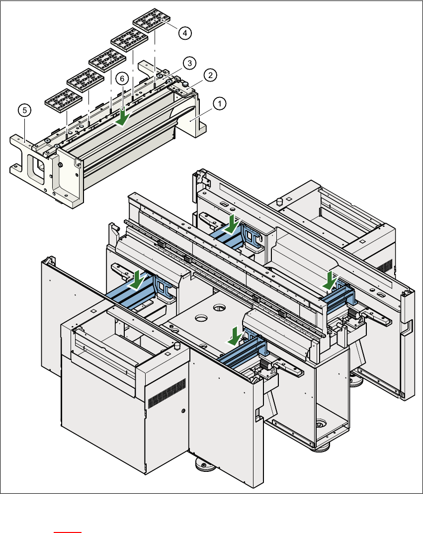
The nozzle changer consists of at least one, and up to five magazines, each with 12 nozzle ga-
rages (see Fig. 5.1 - 1
). The magazines are seated on a common support and each magazine is
centered using two parallel pins and fixed in place with clips.
5.1.2 Technical data
5
Nozzle changer for the 12-segment collect&place head
Dimensions (length x width x height) 472.5 mm x 64 mm x 90 mm
Number of nozzle garages Min. 12 / max. 60
Nozzle types 9xx
Time required to open and close the locking plate < 200 ms
Pneumatic circuit Air line 5.3 bar
5 Station extensions User Manual SIPLACE HS-50
5.1 Nozzle changer for the 12-segment collect&place head Software Version SR.50x.xx 01/2006 US Edition
140
Fig. 5.1 - 1 Position of the nozzle changer
Key to Fig. 5.1 - 1
(1) Used tape guide channel (2) Nozzle discarding device
(3) Nozzle changer (4) Nozzle magazines
(5) Location for optional 2nd nozzle changer
(6) Container for discarded nozzles