00192471-03.pdf - 第142页
5 Station extensions User Manual S IPLACE HS-50 5.1 Nozzle changer for the 12-segment c ollect&place head Software Version SR.50x.xx 01/2006 US Edition 142 Fig. 5.1 - 2 Magazine and nozz le garages (1) Positio ning f…

User Manual SIPLACE HS-50 5 Station extensions
Software Version SR.50x.xx 01/2006 US Edition 5.1 Nozzle changer for the 12-segment collect&place head
141
5.1.3 Mode of operation
The nozzles are seated in nozzle garages and are held in place by a movable locking plate. The
locking plate can be moved 6 mm by a pneumatic cylinder. All the nozzles are either clamped or
released, depending on the position of the plate. The default position of the locking plate, i.e. if
there is no nozzle change in progress, is "closed".
There is a positioning fiducial for position detection on each magazine of the nozzle changer. The
magazine locations are identified by numbers 1 to 5 on the nozzle changer. The nozzle garages
in the magazines are numbered consecutively from 1 to 12 (see Fig. 5.1 - 2
).
PLEASE NOTE 5
Special magazines are available upon request (contact Siemens A&D for details) and will be
numbered differently.
Picking up a nozzle 5
– The Z-axis of the collect&place head moves down.
– The locking plate (item 2 in Fig. 5.1 - 2
) opens and releases the nozzle garages.
– The nozzle is picked up by the sleeve of the collect&place head.
– The Z-axis moves up.
Setting down a nozzle 5
– The locking plate (item 2 in Fig. 5.1 - 2) opens and releases the nozzle garages.
– The Z-axis of the collect&place head moves down and sets the nozzle down.
– The locking plate closes.
– The Z-axis of the collect&place head moves up.
Discarding defective nozzles 5
– The Z-axis of the collect&place head moves down 14 mm towards the discarding device
(item 2 in Fig. 5.1 - 1
) and thus moves the defective nozzle into the hole in the discarding de-
vice.
– The Z-axis moves up again and the nozzle is stripped from the sleeve by spring wires.
– The nozzle drops into the container of the used tape guide channel (item 6 in Fig. 5.1 - 1
).
5 Station extensions User Manual SIPLACE HS-50
5.1 Nozzle changer for the 12-segment collect&place head Software Version SR.50x.xx 01/2006 US Edition
142
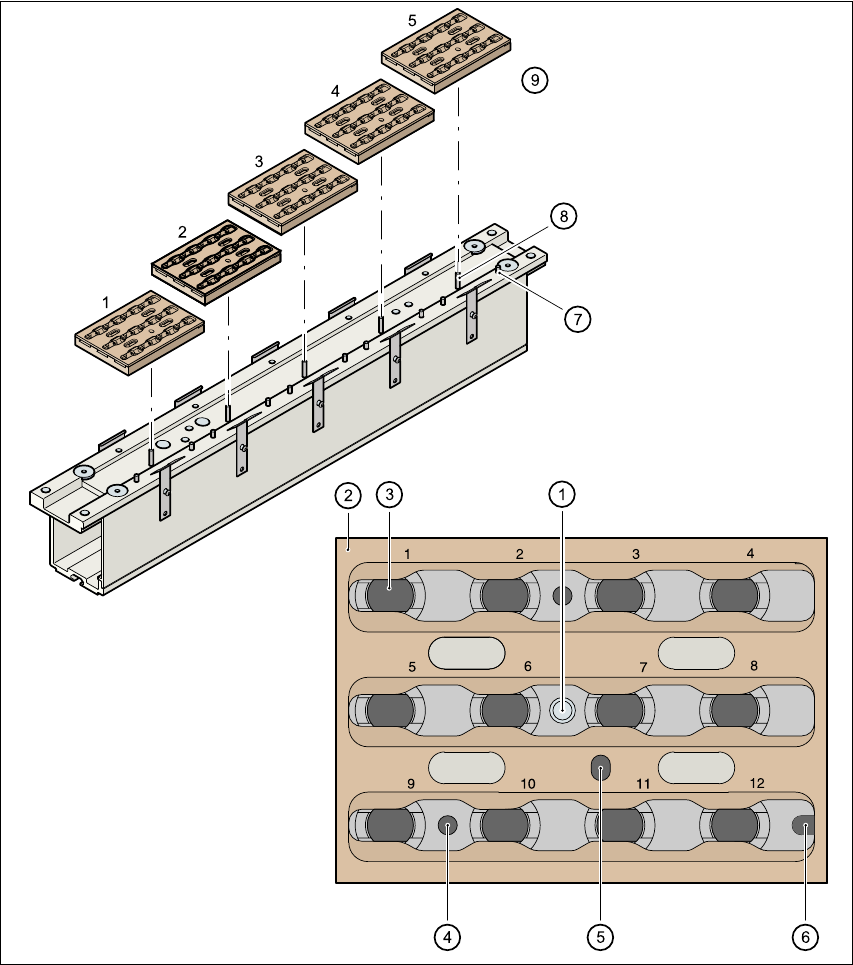
Fig. 5.1 - 2 Magazine and nozzle garages
(1) Positioning fiducial
(2) Locking plate
(3) Nozzle garage
(4) Hole for the parallel pin for centering the magazines
(5) Hole for the parallel pin of the slide mechanism
(6) Slot for the parallel pin for centering the magazines

User Manual SIPLACE HS-50 5 Station extensions
Software Version SR.50x.xx 01/2006 US Edition 5.1 Nozzle changer for the 12-segment collect&place head
143
(7) Parallel pin for centering the magazines
(8) Parallel pins for opening and closing the locking plate
(9) Magazines
5.1.4 Notes on operation
Æ
When you fill a magazine with a certain nozzle type for the first time, attach an adhesive label
to identify the type.
PLEASE NOTE 5
Only ONE
nozzle type must be used in each magazine.
Fill the magazines off the machine and always replace complete magazines. 5
Æ Open the locking plate and place the nozzles in the nozzle garages.
Æ Close the locking plate so that the nozzles cannot drop out of the magazines.
CAUTION 5
Before you fill magazine, make sure that all the nozzles on the collect&place head have been
returned to their magazines. 5
Æ See the UNIX line computer operating instructions for programming the nozzle changers on
the line computer.
PLEASE NOTE 5
Æ Do not allow components to drop onto the magazines. If they do, they could jam the locking
plate.
Æ Do not allow components to drop onto free feeder module locations because they will stick to
the magnetic bar. Production may have to be interrupted if the feeder modules are not placed
on the component table correctly. You should therefore regularly clean the magazines and free
locations.