00192471-03.pdf - 第15页
User Manual SIPLAC E HS-50 1 Introduction Software Version SR.50x.xx 01/2006 US Edition 1.7 Abbreviations 15 1.6. 3 Revisions since 0 1/2006 e ditio n 1 1.7 Abbreviations 1 New or modifie d Chapter / Section R evisio n i…

1 Introduction User Manual SIPLACE HS-50
1.6 Revision index Software Version SR.50x.xx 01/2006 US Edition
14
1.6 Revision index
1
1.6.1 Revisions since 11/2000 edition
1
1.6.2 Revisions since 01/2001 edition
1
Instructions Software version Issue
First draft HS-50 Provisional User Manual
5.01 09/98
Revision of HS-50 User Manual
5.01 01/99
Revision of HS-50 User Manual
5.01.03 12/99
Revision of HS-50 User Manual
5.02 11/2000 US
Revision of HS-50 User Manual
5.02 01/2001 US
Revision of HS-50 User Manual
5.0x 01/2006 US
New or modified Chapter / Section
Structure of the User Manual
1.2
Description of the machine
1.8
Overview of the modules - placement heads
1.16
Overview of the modules - PCB conveyor
1.18
Warning signs on the placement system
2.1.9
Additional warning signs for the NAFTA region
2.1.10
Residual voltages in the servo unit and discharge times
2.3
3 x 8 mm S feeder for 0201/0402 components
4.2.3
PCB barcode
5.4
Ceramic substrate centering
5.5
Optical centering with the multicolor PCB camera
5.5.6
Fine calibration
5.8
New or modified Chapter / Section
Warning signs on the placement system
2.1.9
Additional warning signs for the NAFTA region
2.1.10
Safety instructions for processing capacitors based on powdered metal
2.1.15
Feeders
4.1.1
Safety instructions for processing capacitors based on powdered metal
4.1.2
12 mm S module for capacitors based on powdered metal, model C/D
4.2.5
12 mm S module for capacitors based on powdered metal, model E
4.2.6
Optical centering with oblique lighting
5.5.5
Vacuum tooling
5.9

User Manual SIPLACE HS-50 1 Introduction
Software Version SR.50x.xx 01/2006 US Edition 1.7 Abbreviations
15
1.6.3 Revisions since 01/2006 edition
1
1.7 Abbreviations
1
New or modified Chapter / Section
R
evision index 1.6
Abbreviations 1.7
Use as prescribed 2.1.3
Failure to use as prescribed 2.1.4
Important notes on operational safety 2.1.5
Safety instructions for laser units 2.1.6
Safety instructions on permanent magnets 2.1.7
Important notes on environmentally-friendly disposal of materials and components 2.1.8
C&P 1 Collect&Place 1
C&P12 1 Collect&Place head with 12 segments 1
CO 1 Component 1
DC 1 Dual conveyor 1
DCA 1 Direct Chip Attach 1
ESD 1 Electrostatically-sensitive group of components 1
ESD 1 Electrostatic Sensitive Device 1
FC 1 Flip chip 1
GND 1 Ground 1
IC 1 Integrated circuit 1
MC 1 Machine controller 1
OSC 1 Odd Shaped Components 1
PA 1 Placement area 1
PCB 1 Printed circuit board 1
SC 1 Single conveyor 1
SC 1 Station computer 1
SMD 1 Surface Mounted Device 1
VS 1 Vision system 1
WLAN 1 Wireless Local Network 1
1 Introduction User Manual SIPLACE HS-50
1.8 Description of the machine Software Version SR.50x.xx 01/2006 US Edition
16
1.8 Description of the machine
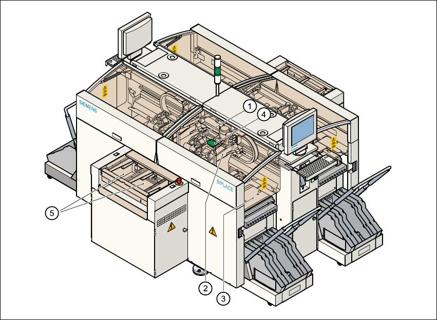
1.8.1 Functional description
The automatic placement system is a high-performance placement system with four gantry axis
systems. A PCB vision module and a star-shaped 12-segment collect&place head are mounted
on each gantry. Collect&place heads equipped with a component vision module pick up the com-
ponents from stationary feeder modules and insert them into the PCB clamped in the PCB con-
veyor. 1
1
Fig. 1.8 - 1 Functional description of the placement system
(1) 12-segment collect&place head/DLM1 with component vision module
(2) Gantry axis system with PCB vision module
(3) Stationary component feeder
(4) Clamped printed circuit board (PCB)
(5) PCB conveyor (dual conveyor option)
1