00192471-03.pdf - 第153页
User Manual SIPLACE HS-50 5 Station extensions Software Version SR.50x.xx 01/2006 US Edition 5.4 PCB barcode 153 5.4 PCB barcode 5.4. 1 Ove rview The PCB barcode r eader is used to a utomatic ally reco rd and de code b a…

5 Station extensions User Manual SIPLACE HS-50
5.3 Dual conveyor Software Version SR.50x.xx 01/2006 US Edition
152
5.3.6 Automatic width adjustment on the dual conveyor
PLEASE NOTE 5
The conveyor setpoint width relates to both conveyor belts. When the command is received, the
conveyor belts are set to the setpoint width one after another.
5.3.7 Technical data - dual conveyor
5
5.3.8 Maintenance
The individual conveyor belts and the additional lifting table require the same maintenance as the
standard conveyor. Each conveyor belt must be maintained as described in the maintenance in-
structions.
Fixed conveyor edge Right (standard), left (optional)
PCB format 50 mm x 50 mm to 368 mm x 216 mm
2" x 2" to 14.5" x 8.5"
PCB thickness 0.3 mm to 4.5 mm
Maximum PCB curvature On top: 4.5 mm - PCB thickness
On bottom: 0.3 mm + PCB thickness
Clearance underneath PCB Standard: 25 mm
Option: Up to 40 mm
PCB conveyor height 830 ± 15 mm (standard)
900 ± 15 mm (option)
930 ± 15 mm (option)
950 ± 15 mm (SMEMA option)
Type of interface Siemens (standard)
SMEMA (option)
Clear guide edge of component 3 mm
PCB changeover time 2.5 s
Type of transportation asychronous
Components on each conveyor same
PCB width on each conveyor same
Ink spot recognition possible
Automatic width adjustment possible

User Manual SIPLACE HS-50 5 Station extensions
Software Version SR.50x.xx 01/2006 US Edition 5.4 PCB barcode
153
5.4 PCB barcode
5.4.1 Overview
The PCB barcode reader is used to automatically record and decode barcodes on PCBs. The
PCB barcode reader sends the read data via its serial interface to the machine controller for fur-
ther processing.
Fig. 5.4 - 1 PCB barcode block diagram
The PCB barcode readers are installed on the input side of the placement machine, above and
below the PCB conveyor, so that barcode labels on the topside and underside of the PCBs can
be read.
A maximum of four PCB barcode readers may be retrofitted in order to read the topside and un-
derside of the PCB on the transport track.
Device number
1
Barcode
reader
topside
Distribution
board
Transport
controller,
right
Barcode
reader
underside
2
3
Barcode
reader
topside
Distribution
board
Transport
controller,
left
Barcode
reader
underside
4
Machine
controller
Station
computer
Line
computer
LAN
CAN
bus
V-24V-24
5 Station extensions User Manual SIPLACE HS-50
5.4 PCB barcode Software Version SR.50x.xx 01/2006 US Edition
154
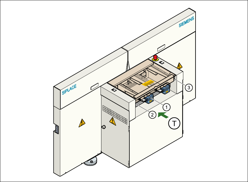
Fig. 5.4 - 2 Position of the modules on the input side of the placement machine
(1) PCB barcode reading head
(2) Profiled rail for ‘underside’ PCB barcode reader
(3) Profiled rail for ‘topside’ PCB barcode reader
(T) Direction of PCB transport
The PCB barcode readers are fixed to the top and bottom profiled rail using retainers. These can
be positioned as required on the profiled rails, and aligned with respect to the barcode labels. De-
pending on the position of the barcode strips, the barcode reader can be attached in a few simple
steps so that the strips can be read parallel to or across the PCB transport direction.