00192471-03.pdf - 第154页
5 Station extensions User Manual S IPLACE HS-50 5.4 PCB barcode Software Version SR.50x. xx 01/2006 US E dition 154 Fig. 5.4 - 2 Position of the modules on t he input side of the placement machine (1) PCB barcod e readin…

User Manual SIPLACE HS-50 5 Station extensions
Software Version SR.50x.xx 01/2006 US Edition 5.4 PCB barcode
153
5.4 PCB barcode
5.4.1 Overview
The PCB barcode reader is used to automatically record and decode barcodes on PCBs. The
PCB barcode reader sends the read data via its serial interface to the machine controller for fur-
ther processing.
Fig. 5.4 - 1 PCB barcode block diagram
The PCB barcode readers are installed on the input side of the placement machine, above and
below the PCB conveyor, so that barcode labels on the topside and underside of the PCBs can
be read.
A maximum of four PCB barcode readers may be retrofitted in order to read the topside and un-
derside of the PCB on the transport track.
Device number
1
Barcode
reader
topside
Distribution
board
Transport
controller,
right
Barcode
reader
underside
2
3
Barcode
reader
topside
Distribution
board
Transport
controller,
left
Barcode
reader
underside
4
Machine
controller
Station
computer
Line
computer
LAN
CAN
bus
V-24V-24
5 Station extensions User Manual SIPLACE HS-50
5.4 PCB barcode Software Version SR.50x.xx 01/2006 US Edition
154
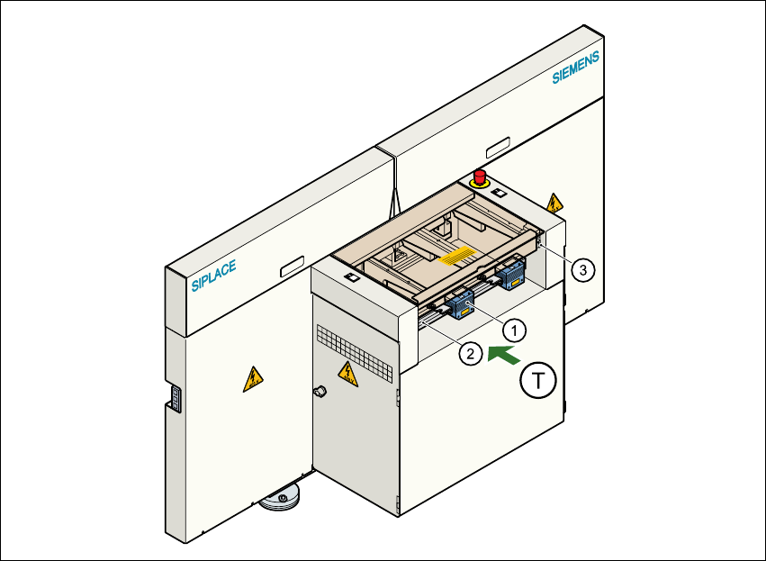
Fig. 5.4 - 2 Position of the modules on the input side of the placement machine
(1) PCB barcode reading head
(2) Profiled rail for ‘underside’ PCB barcode reader
(3) Profiled rail for ‘topside’ PCB barcode reader
(T) Direction of PCB transport
The PCB barcode readers are fixed to the top and bottom profiled rail using retainers. These can
be positioned as required on the profiled rails, and aligned with respect to the barcode labels. De-
pending on the position of the barcode strips, the barcode reader can be attached in a few simple
steps so that the strips can be read parallel to or across the PCB transport direction.
User Manual SIPLACE HS-50 5 Station extensions
Software Version SR.50x.xx 01/2006 US Edition 5.4 PCB barcode
155
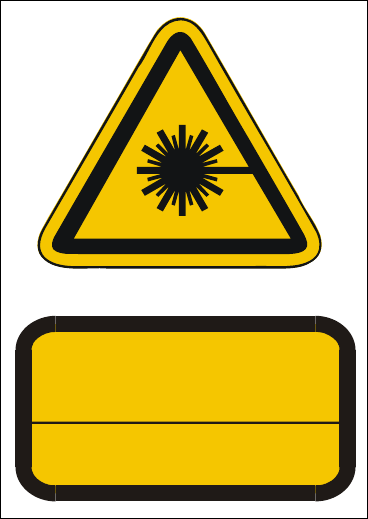
5.4.2 Laser safety instructions
Laser radiation
The radiation from the laser diode (infrared or IR
light) of the PCB barcode reader is harmful to the hu-
man eye,
Æ so you should never look into the laser beam.
Æ Never direct the PCB barcode reader into other
people’s eyes.
Æ When installing the barcode reader, make sure
that the laser beam cannot be not reflected during
use.
If you open the housing during use, the scanning cy-
cle will continue, and the laser diode will continue to
switch on.
The laser beam output at the barcode template win-
dow does not exceed 1.0 mW. The PCB barcode
reader thus conforms to protection class 2.
Fig. 5.4 - 3 Laser safety instructions for the PCB barcode reader
5.4.3 Functional description
5.4.3.1 PCB barcode reader for the single conveyor
The SIPLACE PCB barcode reader supports the flexible manufacture of SMD products, and in-
creases placement reliability. It recognizes all the code types conventionally used in industrial ap-
plications.
The laser scanner reads the barcode label on the topside or underside of each incoming PCB as
they are transported onto the input conveyor. The barcode data enables the line computer to au-
tomatically select the correct barcode allocation list from the previously created barcode assign-
ment list, and sends it to the station. If a barcode filter was defined, only the data that is identified
as relevant will be compared in the barcode. This procedure is carried out time neutrally during
placement of the PCB already in the machine. If several PCBs with the same barcode enter in
succession, the program is only transferred the first time. The following requirements apply to all
products to be produced using the PCB barcode:
– The component set-up must be identical on all the machines on the line
– All PCBs must be of the same width
ATTENTION
LASER RADIATION
DO NOT LOOK INTO THE BEAM
CLASS 2 LASER PRODUCT
EN 60825 1991
Max. output radiation: 1.0 mW
Wavelength: 670 nm