00192471-03.pdf - 第16页
1 Introduction User Manual SIPLACE HS-50 1.8 Description of t he machine Software Version SR.50x.xx 01/2006 US Edition 16 1.8 Des cription of the machine 1.8.1 Functional description The autom atic pla cement sy stem is …

User Manual SIPLACE HS-50 1 Introduction
Software Version SR.50x.xx 01/2006 US Edition 1.7 Abbreviations
15
1.6.3 Revisions since 01/2006 edition
1
1.7 Abbreviations
1
New or modified Chapter / Section
R
evision index 1.6
Abbreviations 1.7
Use as prescribed 2.1.3
Failure to use as prescribed 2.1.4
Important notes on operational safety 2.1.5
Safety instructions for laser units 2.1.6
Safety instructions on permanent magnets 2.1.7
Important notes on environmentally-friendly disposal of materials and components 2.1.8
C&P 1 Collect&Place 1
C&P12 1 Collect&Place head with 12 segments 1
CO 1 Component 1
DC 1 Dual conveyor 1
DCA 1 Direct Chip Attach 1
ESD 1 Electrostatically-sensitive group of components 1
ESD 1 Electrostatic Sensitive Device 1
FC 1 Flip chip 1
GND 1 Ground 1
IC 1 Integrated circuit 1
MC 1 Machine controller 1
OSC 1 Odd Shaped Components 1
PA 1 Placement area 1
PCB 1 Printed circuit board 1
SC 1 Single conveyor 1
SC 1 Station computer 1
SMD 1 Surface Mounted Device 1
VS 1 Vision system 1
WLAN 1 Wireless Local Network 1
1 Introduction User Manual SIPLACE HS-50
1.8 Description of the machine Software Version SR.50x.xx 01/2006 US Edition
16
1.8 Description of the machine
1.8.1 Functional description
The automatic placement system is a high-performance placement system with four gantry axis
systems. A PCB vision module and a star-shaped 12-segment collect&place head are mounted
on each gantry. Collect&place heads equipped with a component vision module pick up the com-
ponents from stationary feeder modules and insert them into the PCB clamped in the PCB con-
veyor. 1
1
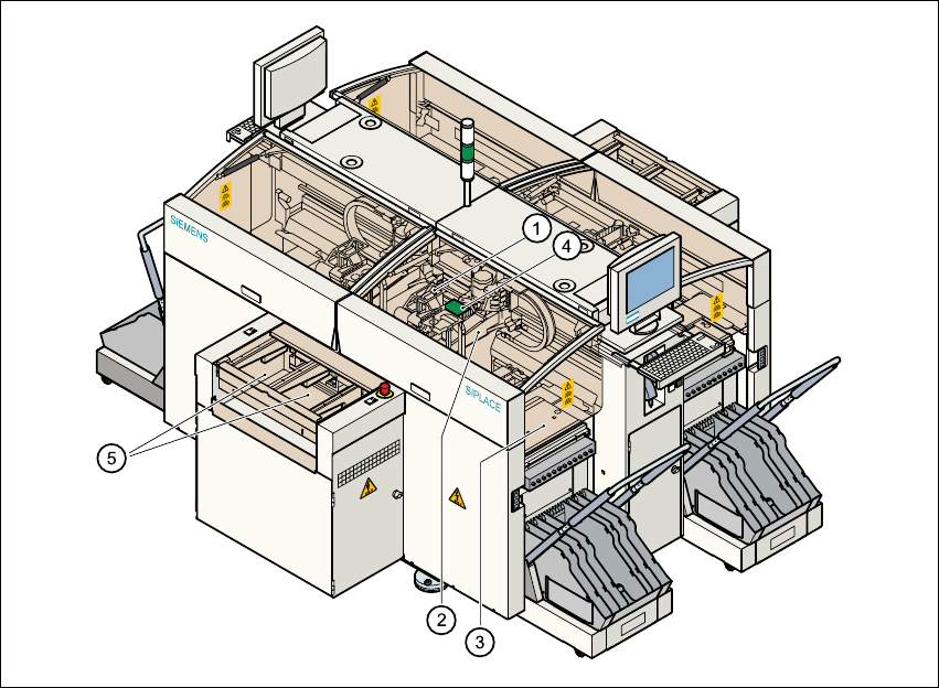
Fig. 1.8 - 1 Functional description of the placement system
(1) 12-segment collect&place head/DLM1 with component vision module
(2) Gantry axis system with PCB vision module
(3) Stationary component feeder
(4) Clamped printed circuit board (PCB)
(5) PCB conveyor (dual conveyor option)
1
User Manual SIPLACE HS-50 1 Introduction
Software Version SR.50x.xx 01/2006 US Edition 1.8 Description of the machine
17
The concept behind the automatic placement system 1
– with its stationary feeder modules,
– PCBs that do not move during placement
– and positionable placement heads
has a number of significant benefits: 1
– For example, the flexible 12-segment collect&place heads combined with automatic nozzle
changers enable the nozzle configuration to be changed temporarily and automatically
adapted to receive different component sizes. You can also optimize the traversing paths and
the placement sequence.
– With stationary feeder modules, even the tiniest components are picked up reliably.
– The components cannot slip on the PCB during placement (as is often the case with moving
PCBs) since the PCB does not move.
– Sophisticated optical centering systems (vision modules) for components and PCBs also en-
sure high component positioning accuracy.
– Components can be topped up and tapes can be spliced without stopping the machine.
– Prepared component tables enable the placement system to be retooled without long stop-
pages.