00192471-03.pdf - 第167页
User Manual SIPLACE HS-50 5 Station extensions Software Version SR.50x.xx 01/2006 US Edition 5.5 Ceramic substrate centering 167 base material, such as cera mic or C EM. Fiducia ls cove red with so lder resi st can al so…
5 Station extensions User Manual SIPLACE HS-50
5.5 Ceramic substrate centering Software Version SR.50x.xx 01/2006 US Edition
166
5.5.6 Optical centering with the multicolor PCB camera
5.5.6.1 General
As an option, a multicolor PCB camera can be installed in place of the sub-gantry camera. The
multicolor PCB camera offers four different types of illumination. This greatly increases fiducial
recognition and thus the centering accuracy.
5
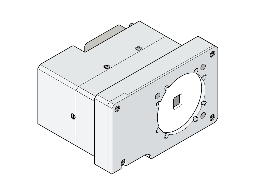
Fig. 5.5 - 4 Multicolor PCB camera
5.5.6.2 Types of illumination for the multicolor PCB camera
The following types of illumination can be selected on the multicolor PCB camera.
– Standard lighting
This mixture of white and infrared lighting can be used to detect a broad range of fiducials. The
image contrast can be improved by varying the illumination, thus optimizing the centering of
different fiducials.
– White lighting
This type of illumination is used for standard PCBs with tinned fiducials.
– Blue oblique lighting:
In most cases, this can be used to greatly improve the contrast with bright fiducials on a light
User Manual SIPLACE HS-50 5 Station extensions
Software Version SR.50x.xx 01/2006 US Edition 5.5 Ceramic substrate centering
167
base material, such as ceramic or CEM. Fiducials covered with solder resist can also be
detected better on a light background.
– Infrared lighting
This type of illumination is particularly useful for fiducials that are covered with solder resist or
for fiducials on flex materials. It is also sometimes possible to improve recognition of silver/
platinum fiducials on ceramic. This should be tested by carrying out a test centering /
placement run.
5 Station extensions User Manual SIPLACE HS-50
5.6 PCB data transfer Software Version SR.50x.xx 01/2006 US Edition
168
5.6 PCB data transfer
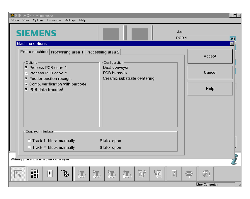
5.6.1 Functional description
The ’Machine options’ menu contains a ’PCB data transfer’ option. The aim of this function is to
increase the placement system’s performance on the line. To do this, an entire PCB is measured
at the
first
placement station and the associated fiducial, single circuit, ink spot, etc. data is deter-
mined, saved and sent to the next station. At subsequent stations, the data is then determined for
two fiducial positions only. These two fiducial positions are then used to correct the position for the
PCB to be processed at each station. It is thus not necessary to measure the entire PCB again,
together with its single circuits, ink spots etc.
5.6.2 Activating the ’PCB data transfer’ option
5
Fig. 5.6 - 1 Machine option: PCB data transfer