00192471-03.pdf - 第169页
User Manual SIPLACE HS-50 5 Station extensions Software Vers ion SR.50x.xx 01/2006 US Edition 5.6 PCB dat a transfer 169 Æ Clic k on the ’ Machine options’ but ton in t he basic v iew . The ’Ma chine op tions’ wi ndow op…
5 Station extensions User Manual SIPLACE HS-50
5.6 PCB data transfer Software Version SR.50x.xx 01/2006 US Edition
168
5.6 PCB data transfer
5.6.1 Functional description
The ’Machine options’ menu contains a ’PCB data transfer’ option. The aim of this function is to
increase the placement system’s performance on the line. To do this, an entire PCB is measured
at the
first
placement station and the associated fiducial, single circuit, ink spot, etc. data is deter-
mined, saved and sent to the next station. At subsequent stations, the data is then determined for
two fiducial positions only. These two fiducial positions are then used to correct the position for the
PCB to be processed at each station. It is thus not necessary to measure the entire PCB again,
together with its single circuits, ink spots etc.
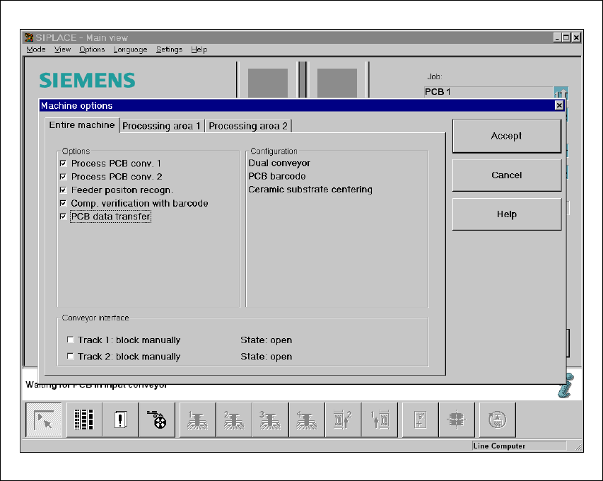
5.6.2 Activating the ’PCB data transfer’ option
5
Fig. 5.6 - 1 Machine option: PCB data transfer

User Manual SIPLACE HS-50 5 Station extensions
Software Version SR.50x.xx 01/2006 US Edition 5.6 PCB data transfer
169
Æ Click on the ’Machine options’ button in the basic view.
The ’Machine options’ window opens.
Æ In the ’Options’ box, check the ’PCB data transfer’ option for the station concerned.
Æ Click on the ’OK’ button. The ’PCB data transfer’ option is now active.
PLEASE NOTE: The ’PCB data transfer’ option can only be used in conjunction with a PCB bar-
code reader. 5
5 Station extensions User Manual SIPLACE HS-50
5.7 Feeder position recognition Software Version SR.50x.xx 01/2006 US Edition
170
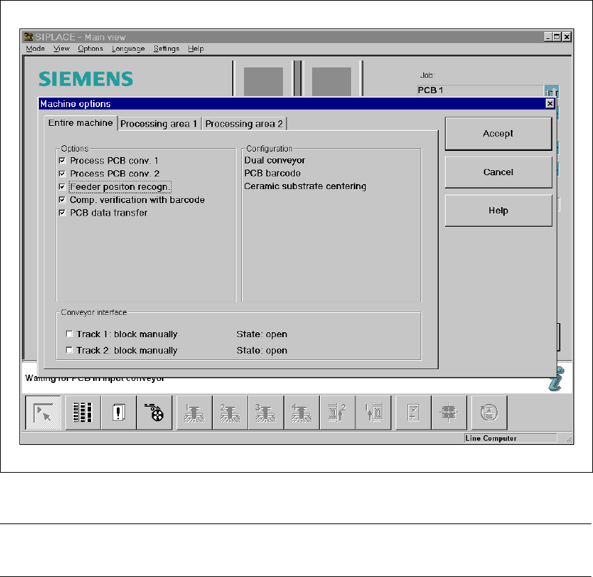
5.7 Feeder position recognition
If the feeder modules are equipped with positioning fiducials, the fiducials can be measured.
If the "Conveyor position detection" function has been selected on the line computer, the function
will also appear in the Machine options. It can then be activated or deactivated at each station.
Fig. 5.7 - 1 Feeder position recognition
PLEASE NOTE 5
The "Feeder position recognition" function is always deactivated when the station is switched on.
If a track has been entered in the cluster data, the PCB camera on the feeder module will approach
the position of the centering fiducial. Any centering fiducial offset determined during the measure-
ment will then be assigned to this track and added to the pick-up position during the pick-up op-
eration.