00192471-03.pdf - 第23页
User Manual SIPLAC E HS-50 1 Introduction Software Vers ion SR.50x.xx 01/2006 US Edition 1.12 Dimens ions and weight of the plac ement system 23 1.12 Dimensions and weight of the placeme nt system 1.12.1 Dimensions of th…

1 Introduction User Manual SIPLACE HS-50
1.11 Technical data - compressed air supply Software Version SR.50x.xx 01/2006 US Edition
22
1.11 Technical data - compressed air supply
1.11.1 Technical data - compressed air specification
Maximum particle size by density, based on ISO/DIS 8573-1 (class 1) 1
1.11.2 Technical data - noise emissions
1.11.3 Technical data - admissible environmental influences
Compressed air pressure supply min 6.5 bar
Compressed air consumption 950 Nl/min.
Operating pressure 5.5 bar ± 0.5 bar
Particle size 0.1 µm
Particle density 0.2 mg/m³
Maximum oil content (class 1) Particle density 0.01 mg/m³
Dew point under pressure (class 4) Dew point +3°
Maximum noise generation 74 dB (A)
Ambient temperature Between 15°C and 35°C
Atmospheric humidity 30 to 75%
(but no higher than 45% on average in order to prevent
any possibility of condensation on the machine.)
User Manual SIPLACE HS-50 1 Introduction
Software Version SR.50x.xx 01/2006 US Edition 1.12 Dimensions and weight of the placement system
23
1.12 Dimensions and weight of the placement system
1.12.1 Dimensions of the placement system
1
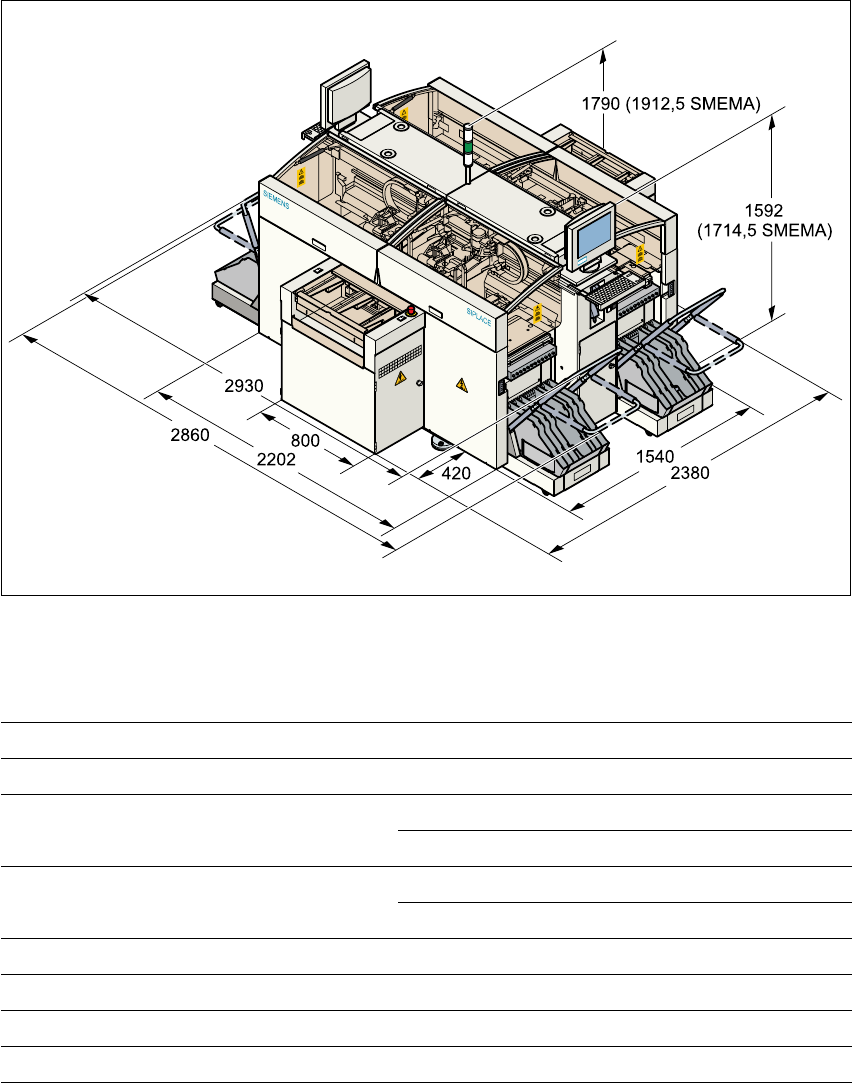
Fig. 1.12 - 1 Dimensions of the placement system
1.12.2 Technical data - dimensions, weight
1
Length 2380 mm including conveyor belts
Width 3150 mm including brackets
Height with warning lamp 1790 mm standard height
1912.5 mm SMEMA height
Ground clearance 110 mm standard height
232.5 mm SMEMA height
Weight of basic module 2800 kg
Weight fully equipped 3500 kg
Admissible load per unit area on foundation 1000 kg/m²
Load per unit area on mounting feet 3.79 kg/cm²
1 Introduction User Manual SIPLACE HS-50
1.12 Dimensions and weight of the placement system Software Version SR.50x.xx 01/2006 US Edition
24
1.12.3 The placement system’s center of gravity
1
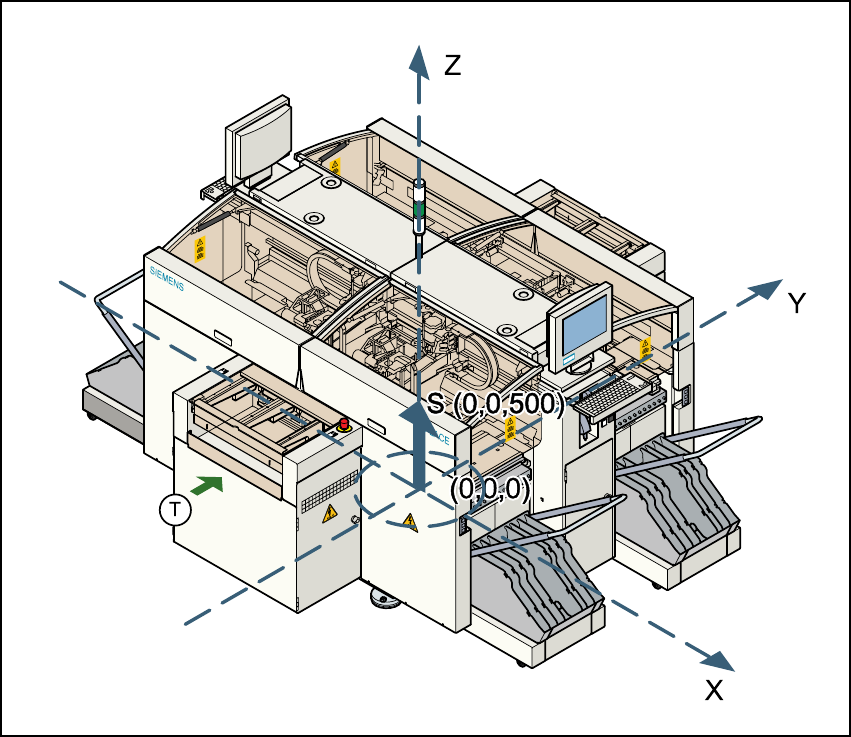
Fig. 1.12 - 2 The placement system’s center of gravity
X coordinate 0 mm 1
Y coordinate 0 mm 1
Z coordinate 500 mm high 1
T PCB transport direction 1
1
These center of gravity coordinates relate to placement systems with a PCB transport height of
830 mm. 1