00192471-03.pdf - 第34页
1 Introduction User Manual SIPLACE HS-50 1.15 Overview o f the modules - gantries Software Version SR.50x.xx 01/2006 US Edition 34 1.15.2 Structure of the X-axis 1 Fig. 1.15 - 2 Structure of the X- axis The X-axi s esse …
User Manual SIPLACE HS-50 1 Introduction
Software Version SR.50x.xx 01/2006 US Edition 1.15 Overview of the modules - gantries
33
1.15 Overview of the modules - gantries
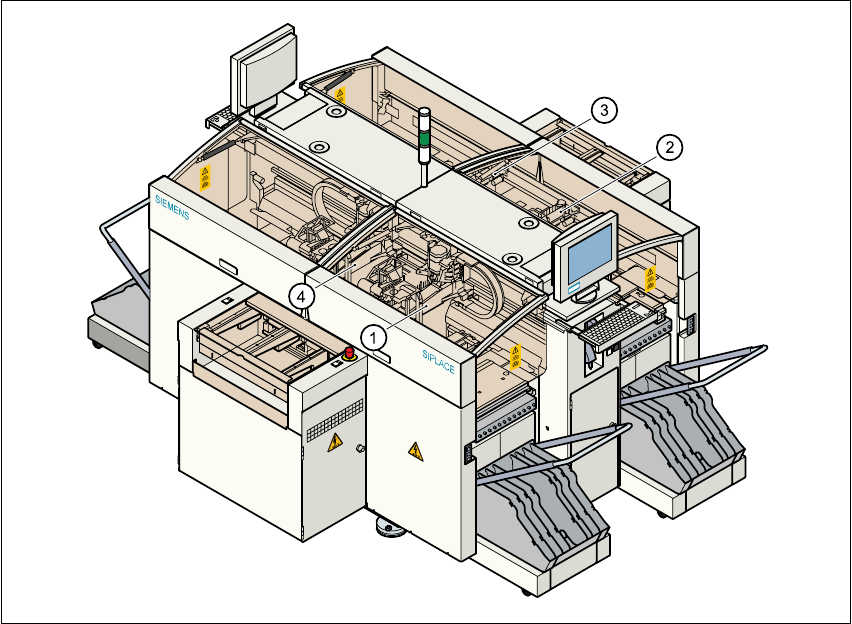
1.15.1 Position of the gantries
1
Fig. 1.15 - 1 Position of the gantries
(1) Gantry 1 (sector 1)
(2) Gantry 2 (sector 2)
(3) Gantry 3 (sector 3)
(4) Gantry 4 (sector 4)
1
The gantry system consists of two functional groups 1
–X-axis
–Y-axis
1
1 Introduction User Manual SIPLACE HS-50
1.15 Overview of the modules - gantries Software Version SR.50x.xx 01/2006 US Edition
34
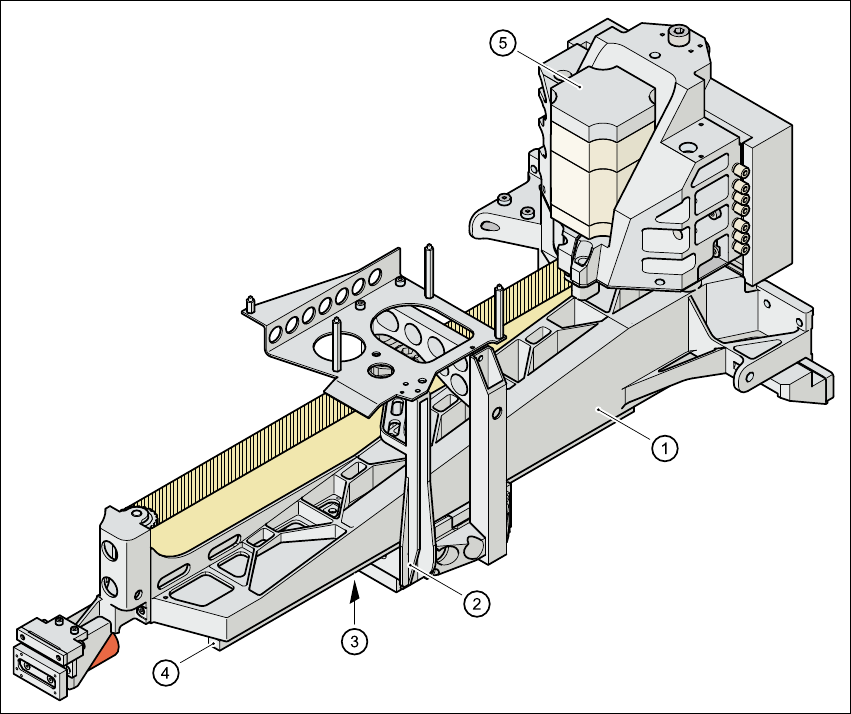
1.15.2 Structure of the X-axis
1
Fig. 1.15 - 2 Structure of the X-axis
The X-axis essentially consists of the following main modules: 1
– gantry arm (1)
– head mount (2)
– linear measuring system (3)
– X-axis guide system (4)
– X-axis three-phase AC servomotor (5)
The head mount holds the following components 1
– sub-gantry camera (camera for the PCB vision module)
– head board
– measuring head for the X-axis measuring system
– collect&place head
User Manual SIPLACE HS-50 1 Introduction
Software Version SR.50x.xx 01/2006 US Edition 1.15 Overview of the modules - gantries
35
1.15.3 Technical data for the X-axis
1
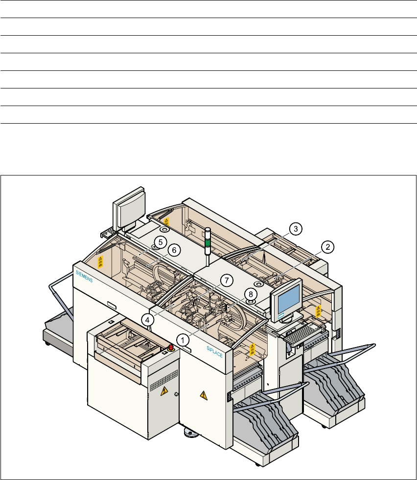
1.15.4 Structure of the Y-axis
1
Fig. 1.15 - 3 Structure of the Y-axis
Drive Three-phase AC servomotor/toothed belt
Maximum speed 2.5 m/sec.
Traversing path 375 mm
Distance measuring system Metal linear scale
Measured length 400 mm
Scale length 420 mm
Resolution 1 µm
(1) Gantry 1 (2) Gantry 2
(3) Gantry 3 (4) Gantry 4
(5) Permanent magnet (6) Guide system
(7) Measuring system (8) Adapter plate