00192471-03.pdf - 第39页
User Manual SIPLAC E HS-50 1 Introduction Software Version SR.50x.xx 01/2006 US Edition 1.17 Overview of the modules - vision modules 39 1.17 O vervi ew of the mo dules - visi on modu les Each placemen t system ha s 1 – …

1 Introduction User Manual SIPLACE HS-50
1.16 Overview of the modules - placement heads Software Version SR.50x.xx 01/2006 US Edition
38
All the components are inserted with the same cycle time. Before the component is inserted, it is
measured by the optoelectronic vision module. 1
– The component vision camera creates an image of the current component.
– The precise position of the component is also determined.
– The package form of the current component is compared against the programmed package
form in order to identify it. Any components that cannot be identified are rejected.
– The turning station turns the component to the required placement position.
1.16.2 Description of the 12-segment collect&place head
– The 12-segment collect&place head works using the "collect & place" principle, i.e. the com-
ponents are held by the nozzles with the aid of a vacuum and, after one complete pick-up cycle,
are placed gently and accurately on the PCB with the aid of forced air. The vacuum in the noz-
zles is also checked several times to determine whether the components were picked up and
set down correctly.
– The "adaptive" sensor stop mode of the z axis compensates for any irregularity of the PCB sur-
face when the components are set down.
– Defective components are rejected and are picked up again during a repair run.
1.16.3 Technical data - 12-segment collect&place head
1
Range of components 0402 to PLCC44, including BGA, µBGA, flip-chip,
TSOP, QFP, PLCC, SO to SO32, DRAM
Component specification
Max. height
Min. lead pitch
Min. bump pitch
Min. ball/bump diameter
Min. dimensions
Max. dimensions
Max. weight
6 mm
0.5 mm
0.35 mm
0.2 mm
0.5 mm x 1.0 mm
18.7 mm x 18.7 mm
2 g
Maximum stroke of the Z axis 16 mm
Programmable set-down force 2.4 to 5.0 N
Max. placement rate 12,500 components/h
Nozzle types 9xx
Angular accuracy ± 0.70° / 4 σ
Placement accuracy ± 90 µm / 4 σ
User Manual SIPLACE HS-50 1 Introduction
Software Version SR.50x.xx 01/2006 US Edition 1.17 Overview of the modules - vision modules
39
1.17 Overview of the modules - vision modules
Each placement system has 1
– four component vision cameras on the placement heads and
– four PCB vision cameras on the underside of the X-axis gantries.
The vision evaluation units are located in the control unit for the placement system and the com-
ponent vision module is used to determine: 1
– the precise position of the components at the nozzle and
– the geometry of the package form.
The PCB vision module uses fiducials on the PCBs to determine: 1
– the position of the PCB,
– its rotation angle
– and the PCB delay.
The PCB vision module also uses fiducials on the feeder modules to determine the exact pick-up
position of components, which is particularly important for small components. 1
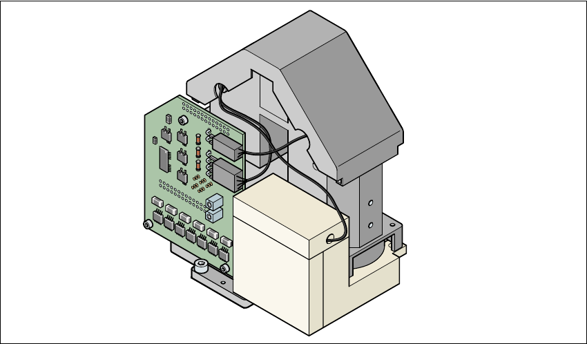
1.17.1 Component vision module on the 12-segment collect&place head
1
Fig. 1.17 - 1 Component vision module on the 12-segment collect&place head
1 Introduction User Manual SIPLACE HS-50
1.17 Overview of the modules - vision modules Software Version SR.50x.xx 01/2006 US Edition
40
1.17.2 Technical data - component vision module on the 12-segment collect&place head
1
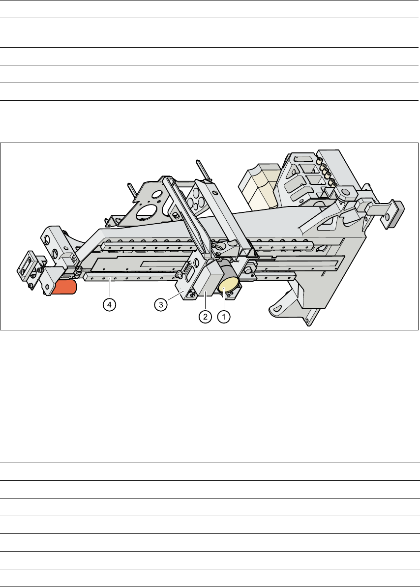
1.17.3 PCB vision module
1
Fig. 1.17 - 2 PCB camera system, gantry viewed from bottom
(1) PCB camera - lens and illumination
(2) Camera amplifier
(3) Head mount
(4) Gantry
1.17.4 Technical data - PCB vision module
1
Maximum component dimensions 0.5 mm x 1.0 mm to 18.7 mm x 18.7 mm
Range of components 0402 to PLCC44 including BGA, µBGA, flip-chip,
TSOP, QFP, PLCC, SO to SO32, DRAM
Min. lead spacing 0.5 mm
Field of view 24 mm x 24 mm
Illumination method Front-lighting (3 levels programmable as required)
Fiducials Up to 3 per placement program
Local fiducials Up to 2 per PCB (may be of different types)
Library size Up to 255 fiducial types - system fiducials ≥ 249
Image processing Gray scale-based correlation
Illumination method Front-lighting
Recognition time per fiducial/ink spot 0.4 s
Field of view 5.7 mm x 5.7 mm