00192471-03.pdf - 第64页
2 Operational Safety User Manual S IPLACE HS-50 2.1 Safety in structions Software Version SR.50x.xx 01/2006 US E dition 64 Æ Swi vel the c omponent table handle u p. The la tching di sk will al so swivel up. PLEA SE NOT …
User Manual SIPLACE HS-50 2 Operational Safety
Software Version SR.50x.xx 01/2006 US Edition 2.1 Safety instructions
63
2
Fig. 2.1 - 6 Label: Laser radiation
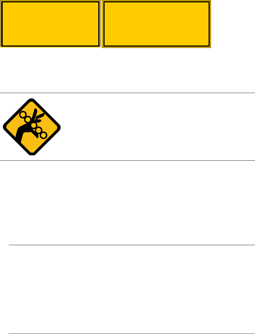
2.1.14 Safety instructions for changing the height of component tables
WARNING 2
The component table must only be converted to modify the default
height by trained Service personnel.
Act with considerable care during the conversion process since
the system contains large weights or compression springs (potential
energy).
2
Converting the component table to suit a different line height 2
Æ Use the placement system’s pneumatic controller to raise the table bed. Then insert a 120mm
spacer block between the table bed and cross-beam, and lower the bed onto the block.
Æ Dismantle the internal paneling.
Æ Swivel the handle down. The latching disk swivels down as well.
Æ Set the screw to the desired dimension and lock in place with the locknut.
PLEASE NOTE:
If you cannot loosen the adjusting screw far enough, the cross-beam must be raised. 2
Æ Fix the lifting device to the cross-beam.
Æ
Carefully
open the cross-beam clamp.
Æ Raise the cross-beam until the end of the tube projects approx. 1mm out of the clamp.
Æ Tighten the cross-beam clamp.
Æ Then turn the adjusting screw to the desired dimension and lock in place with the locknut.
2
Laser radiation
Do not look into beam
Class 2 laser product
2
Attention!
Laser radiation if the cover
is opened and the safety
interlock is bypassed.
Do not look into beam

2 Operational Safety User Manual SIPLACE HS-50
2.1 Safety instructions Software Version SR.50x.xx 01/2006 US Edition
64
Æ Swivel the component table handle up. The latching disk will also swivel up.
PLEASE NOTE:
If you cannot swivel the latching disk up to its end position, the cross-beam must be raised. 2
Æ Fix the lifting device to the cross-beam.
Æ
Carefully
open the cross-beam clamp.
Æ Raise the cross-beam until the end of the tube projects approx. 1mm out of the clamp.
Æ Tighten the cross-beam clamp.
Æ Then turn the adjusting screw to the desired dimension and lock in place with the locknut.
Æ Then
carefully
open the cross-beam clamp.
Æ Lower the cross-beam until the adjusting screw comes into contact with the latching disk.
Æ Tighten the cross-beam clamp.
Æ Then check the distance between the cross-beam and floor.
Æ Refit the internal paneling.
Æ Raise the table bed and remove the spacer block.
User Manual SIPLACE HS-50 2 Operational Safety
Software Version SR.50x.xx 01/2006 US Edition 2.1 Safety instructions
65
2.1.15 Safety instructions for processing capacitors based on powdered metal
There is a risk associated with processing capacitors based on powdered metal (e.g. tantalum). 2
The risk is that 2
– An exothermic reaction, i.e. a sudden build-up of heat, may occur if these components are
damaged. If the ambient conditions are unfavorable, and depending on the capacitance, this
build-up of heat can cause damage.
– This effect can occur when these components are cut.
Please contact your suppliers to clarify whether the components that you handle are affected. 2
In extremely rare cases, this risk can occur in the tape cutter of SIPLACE machines, with the re-
mote possibility of causing a smoldering fire in the waste tape. 2
The ambient conditions are unfavorable if: 2
(1) The components remain on the tape while the set tape cycle is checked (since the operator
can cycle the feeder onward without removing components during this check).
(2) The components remain on the tape, e.g. due to a tear in the cover foil.
(3) The components remain on the tape, and the components or tape do not conform to the
specification, thus increasing the pick-up error rate.
Please follow the instructions given below to minimize the risk when placing capacitors based on
powdered metal. 2
(1) If the component tape is cycled onward manually, the operator must remove any components
remaining in the tape pocket.
(2) If the cover foil tears, the operator must remove any components remaining on the tape.
(3) The waste tape container must be emptied regularly (recommended interval: every hour).
2
CAUTION
To avoid the risk, it is essential to use only feeders that
have been approved for placing such components,
namely:
Article no.: 00141118-01 Model C/D
Article no.: 00141117-01 Model E 2
2
The feeders are labeled as shown
below:
2
Approved for
capacitors based on
metal-powder
Freigegeben für
Kondensatoren auf
Metallpulver-Basis