00192471-03.pdf - 第70页
2 Operational Safety User Manual S IPLACE HS-50 2.2 Safety equipment Software Version SR.50x.xx 01/ 2006 US Edition 70 2.2.3.2 Position of emergency stop butto ns, protective swit ches etc. on the placement system 2 Fig.…
User Manual SIPLACE HS-50 2 Operational Safety
Software Version SR.50x.xx 01/2006 US Edition 2.2 Safety equipment
69
2.2.3 Main switch, emergency stop buttons, protective cover switches
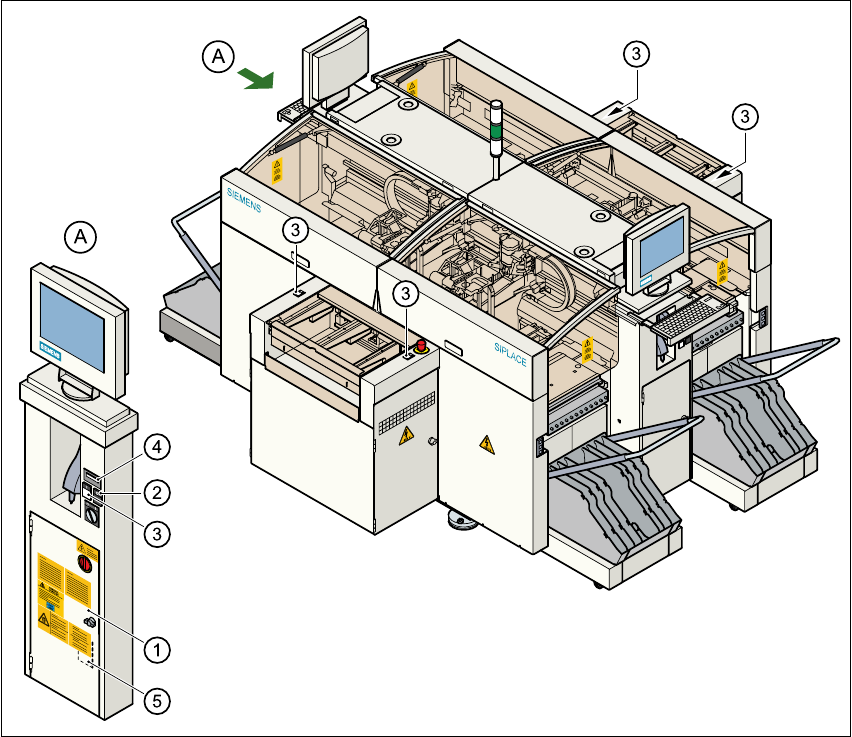
2.2.3.1 Position of main switch, start buttons etc. on the placement system
2
Fig. 2.2 - 4 Position of main switch, start buttons etc. on the placement system
(1) Main switch
(2) Stop buttons (black)
(3) Start buttons (white)
(4) Component counter
(5) Service socket in the power supply unit behind the safety doors
2
2 Operational Safety User Manual SIPLACE HS-50
2.2 Safety equipment Software Version SR.50x.xx 01/2006 US Edition
70
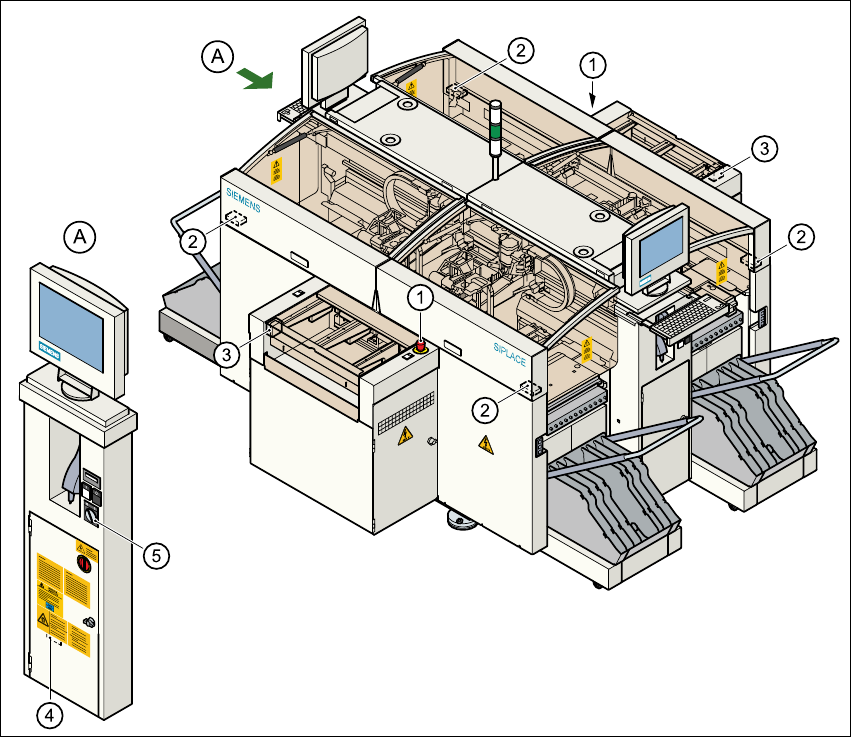
2.2.3.2 Position of emergency stop buttons, protective switches etc. on the
placement system
2
Fig. 2.2 - 5 Emergency stop buttons, protective switches
(1) Emergency-stop buttons
(2) Protective cover switches
(3) Cover switches over the PCB conveyors
(4) Protective contactor combination (PCC) in the power supply unit behind the safety doors
(5) Key switch
Key switch opened: position 0 for normal mode
Key switch closed: position I for service purposes
User Manual SIPLACE HS-50 2 Operational Safety
Software Version SR.50x.xx 01/2006 US Edition 2.2 Safety equipment
71
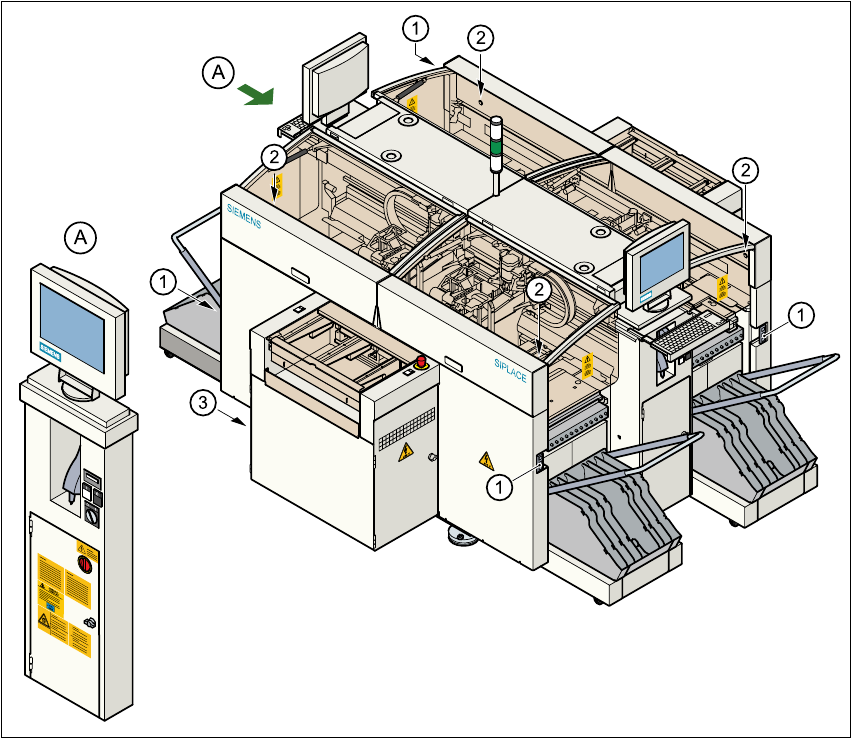
2.2.3.3 Position of UPS, station computer and sockets for connecting the component
change-over tables to the placement system
2
Fig. 2.2 - 6 UPS, station computer, sockets for connecting the component change-over tables
(1) Socket for connecting the component change-over tables
(2) Push-button for raising the component change-over tables with flap down and protective switch
(3) UPS and station computer
2