00192471-03.pdf - 第72页
2 Operational Safety User Manual S IPLACE HS-50 2.2 Safety equipment Software Version SR.50x.xx 01/ 2006 US Edition 72 2.2.3.4 Functional description Main switch in the OFF position (see item 1 in Fig. 2.2 - 4 ) 2 The ma…
User Manual SIPLACE HS-50 2 Operational Safety
Software Version SR.50x.xx 01/2006 US Edition 2.2 Safety equipment
71
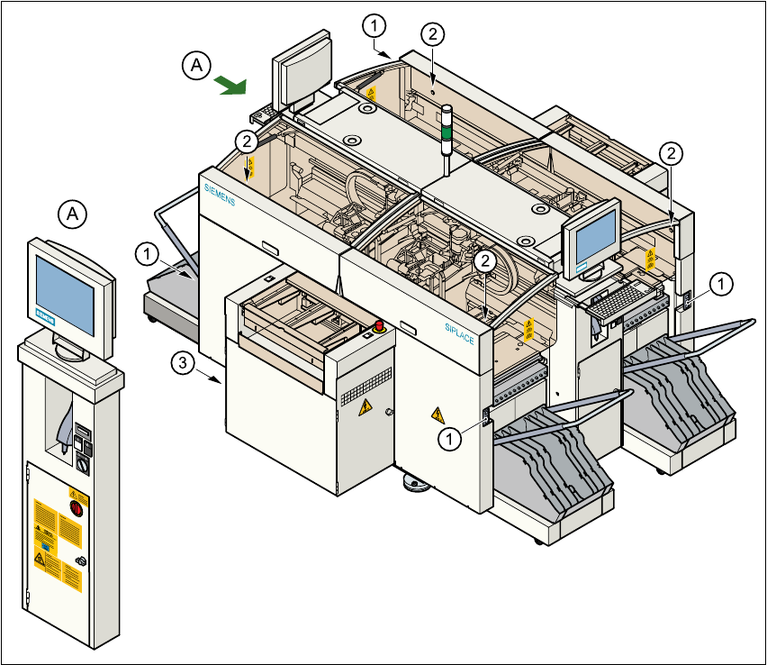
2.2.3.3 Position of UPS, station computer and sockets for connecting the component
change-over tables to the placement system
2
Fig. 2.2 - 6 UPS, station computer, sockets for connecting the component change-over tables
(1) Socket for connecting the component change-over tables
(2) Push-button for raising the component change-over tables with flap down and protective switch
(3) UPS and station computer
2

2 Operational Safety User Manual SIPLACE HS-50
2.2 Safety equipment Software Version SR.50x.xx 01/2006 US Edition
72
2.2.3.4 Functional description
Main switch in the OFF position (see item 1 in Fig. 2.2 - 4
) 2
The main switch disconnects the three phases L1, L2 and L3 from the power supply. 2
DANGER 2
The following components still carry potentially lethal voltages even if the main switch is switched
off: 2
– cable connection terminals 1, 3, and 5 of S1 main switch
– Z1 main power filter
– BU1 service socket
– F1 automatic circuit breaker for the service socket
– The color of all individual wires, which still carry potentially lethal voltages even if the main
switch is switched off is brown.
– The uninterruptible power supply and the station computer may also still carry potentially lethal
voltages when the main switch is switched off.
Æ Incorrect handling of the placement system can therefore result in death or severe injury or
considerable damage to equipment.
Æ Always follow the applicable accident prevention and DIN regulations (particularly DIN EN
60 204, part 1) or the regulations specific to your country.
Æ The safety doors to the power supply unit must only be opened by appropriately qualified and
trained personnel.
Main switch in the ON position 2
After switching on at the main switch, start the station computer and machine controller. All supply
voltages, apart from the link voltages for the gantry axes (200 V) and star axes (100 V), are then
available. 2
Stop button, black (item 2 in Fig. 2.2 - 4) 2
These buttons are used to stop the placement system. 2

User Manual SIPLACE HS-50 2 Operational Safety
Software Version SR.50x.xx 01/2006 US Edition 2.2 Safety equipment
73
Start button, white (item 3 in Fig. 2.2 - 4) 2
After switching on at the main switch, you will be prompted to press the Start button in order to
start the placement system for placement jobs. The same prompt appears if you open the protec-
tive covers or press the emergency stop button. 2
Component counter (Item 4 in Fig. 2.2 - 4) 2
This displays the number of inserted components. 2
Service socket (Item 5 in Fig. 2.2 - 4) 2
The service socket is contained in the power supply unit and is protected by the safety doors. It
can only be used if the placement system is connected to the main power supply via a 5-wire con-
nection (L1, L2, L3, MP and PE). If a 4-wire connection is used, e.g. without N, the socket cannot
be used. 2
Always follow the safety instructions concerning potentially lethal voltages - even when the place-
ment system is switched off. 2
Emergency stop button, latching, with override protection to EN 418 (Item 1 in Fig. 2.2 - 5) 2
The emergency stop button is a red, mushroom-shaped button. It latches in the ON position when
pressed. When you press the emergency stop button, the switching contact of the safety circuit
opens and the protective contactor combination (PCC) trips. The link voltage (200 V) for the gantry
axes is switched off, whereas the link voltage (100 V) for the star axes is reduced to 6 VDC. The
servo amplifiers for the dp and z axes are still supplied with 30 VDC. The signalling contact of the
emergency stop buttons closes and the message "Emergency stop pressed" appears on screen.
The following modules: 2
– PCB conveyor
– PCB clamping
– width adjustment
– PCB stopper and
– used tape cutter
are deactivated. 2
PLEASE NOTE Placement is interrupted and can either be continued or cancelled once the
machine is restored to working order. 2