00195372-0102_AI_Vakuumpumpe_D1D2_DE EN - 第30页
2 Assembly instructi ons for vacuum pump D1 / D2 11/2006 Edition 30 2.5 Modifying the compressed air supply : Switch the placement mach ine off at the main switch and disconnect it from the electricity . : Open the door …

D1 / D2 2 Assembly instructions for vacuum pump
11/2006 Edition
29
2.3 Necessary parts
Description Item no. 2
1 pc D1 Vacuum Pump Connection Kit 00119899-xx 2
consisting of: 2
1 pc DLM2 Vacuum generator for the vacuum pump 03012076-xx 2
1 pc D1/D2 Vacuum distributor 03053022-xx 2
1 pc Vacuum tube 03053080-xx 2
0,2 M Pneumatic tube TUS 0805 B Soft-PU 03005759-xx 2
1 pc T-Fitting QST-6 00320170-xx 2
12 M Siphon pipe- and pressure hose Di 32 HELISPRING 00368279-xx 2
1 pc Y-Fitting HELICONNECT 948 032 00368697-xx 2
6 pc Hose Clamp DIN 3017 NW 32 - 50 00363127-xx 2
1 pc Release tool for Q8 03047090-xx 2
1 pc Release tool for QSC-10H 03051853-xx 2
2
1 pc Anschluss-Kit Vakuumpumpe D2 00119900-xx 2
consisting of: 2
2 pc DLM2 Vacuum generator for the vacuum pump 03012076-xx 2
1 pc D1/D2 Vacuum distributor 03053022-xx 2
12 M Siphon pipe- and pressure hose Di 32 HELISPRING 00368279-xx 2
1 pc Y-Fitting HELICONNECT 948 032 00368697-xx 2
6 pc Hose Clamp DIN 3017 NW 32 - 50 00363127-xx 2
1 pc Release tool for Q8 03047090-xx 2
1 pc Release tool for QSC-10H 03051853-xx 2
2
1 pc Vacuum pump 00119017-xx 2
2
2
The current list of spare parts can be found at www.siplace.com
After logging on, please click “Start” below “SIPLACE Parts Catalogue, easy search for SIPLACE
spare parts!” 2
2.4 Necessary tools and consumables required
– Ballpoint Hex Wrench Kit
– Cable Clips Kit
– Wire Cutters
– Tube Pliers
– Pliers
Depending on the machine set-up the modifying should be finished in about 1 - 1.5 hours. 2
2 Assembly instructions for vacuum pump D1 / D2
11/2006 Edition
30
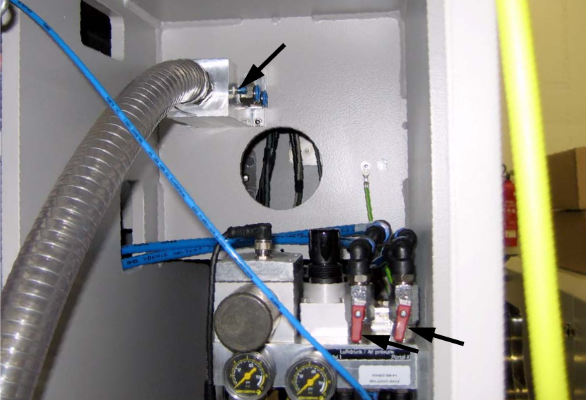
2.5 Modifying the compressed air supply
: Switch the placement machine off at the main switch and disconnect it from the electricity.
: Open the door of the compressed air supply (completely open).
: Fasten the connector in the measurement connection of the vacuum distribution blocks (see
Fig. 2.5.1).
: Put a blanking plug (QSC-4H) into the measurement connection.
: Turn both of the connectors into the vacuum distribution block.
Fig. 2.5.1 Compressed Air Supply with the vacuum distribution block
2
2
2
2
2
2
2
D1 / D2 2 Assembly instructions for vacuum pump
11/2006 Edition
31
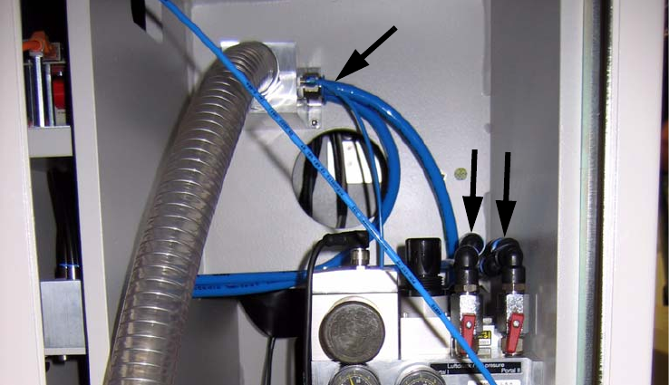
: Mount the vacuum distribution block on the back.
: Close off both compressed air main shut-off valves (red).
Fig. 2.5.2 Compressed Air tubes in the vacuum distribution block
2
: Pull in each case the upper compressed air tube (PUN 12 00344918-) out of the Y fitting (next
to the shut-off valves).
: Put them into the vacuum distribution block
: Put the blanking plugs (QSC-12H from the vacuum distribution) into the open Y pieces next to
the shut-off valves.
2