00195372-0102_AI_Vakuumpumpe_D1D2_DE EN - 第35页
D1 / D2 2 Assembly instructions for vacuum pump 11/2006 Edition 35 : Remove the remaining tubes (p ay attention to the po sitioning) : Remove the entire HF-vacuum gen erator . Fig. 2.6.4 Reequip ped vacuum generator f or…
2 Assembly instructions for vacuum pump D1 / D2
11/2006 Edition
34
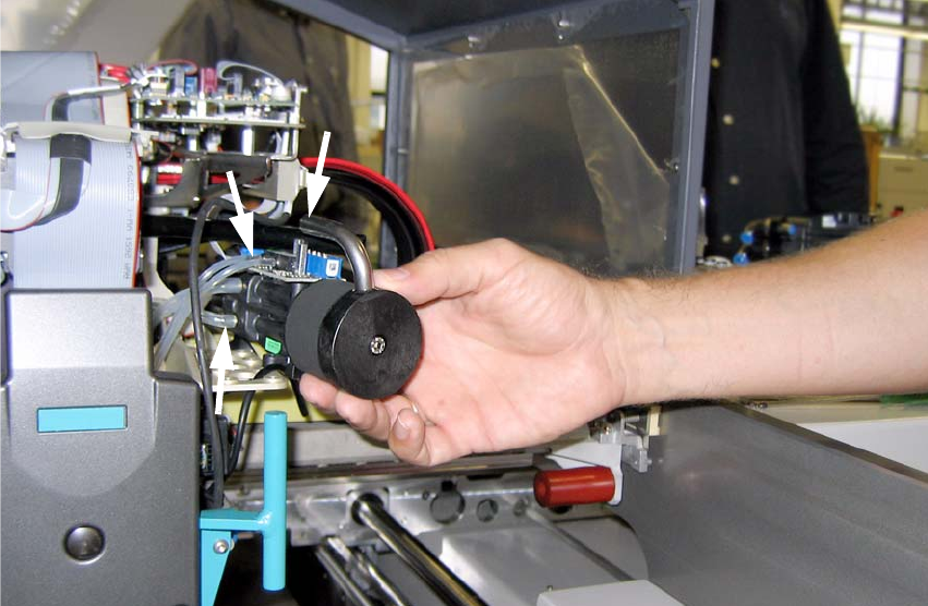
: Remove the 4 fixing bolts from the vacuum generator (pay attention to the washer).
Fig. 2.6.3 Tubing on HF-Vacuum Generator
2
2
2
2
2
2
2
2
2
2
2
2
2
2
2
D1 / D2 2 Assembly instructions for vacuum pump
11/2006 Edition
35
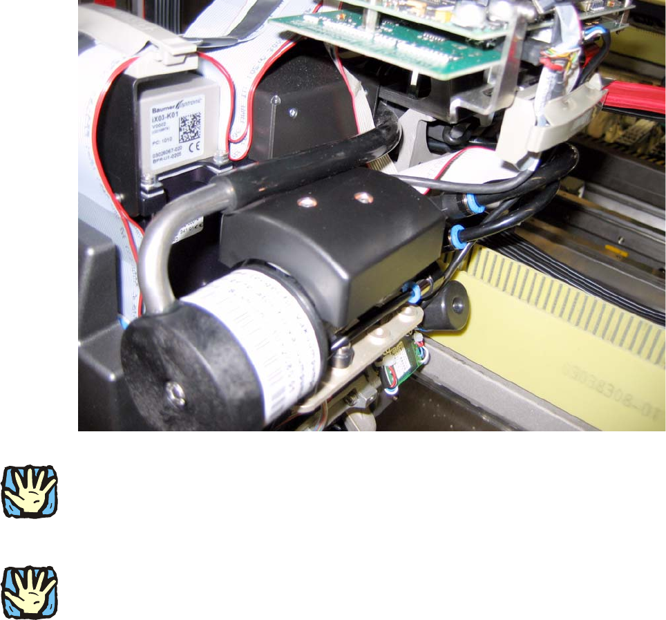
: Remove the remaining tubes (pay attention to the positioning)
: Remove the entire HF-vacuum generator.
Fig. 2.6.4 Reequipped vacuum generator for vacuum pump DLM2 (not air-permeable cylinder)
2
The transparent tubes as before –do not attach crosswise therefore!
: Put the tubes correctly into the vacuum generator for vacuum pump DLM2.
2
Pay attention to the pins when attaching. This plug could be attached also misplaced, leading to
damage! 2
: Attach the ribbon cable to the ga
ntry distribution plate.
: Fasten the vacuum generator (4 screws and disks).
: Loosen the screw on the front side, to turn the pipe correctly and you fix them again afterwards.
: Fasten the cover of the vacuum generator plate (2 screws).
: Fix the cables with the cable clip at the gantry distributor.
2
: Before powering on complete the ”Finishing Work” (Chapter 2.9).
2 Assembly instructions for vacuum pump D1 / D2
11/2006 Edition
36
2.7 Modifying the piping
1 pc Anschluss-Kit für Köpfe D1 03053075-xx 2
bestehend aus: 2
1 Schlauch Vakuum 03053080-xx 2
0.05 M Pneumatikschlauch PUN 6 2
1 T-fitting QST-6 00320170-xx 2
1 Stopfen QSC-6H 2
1 Entriegelungswerkzeug für Q8 03047090-xx 2
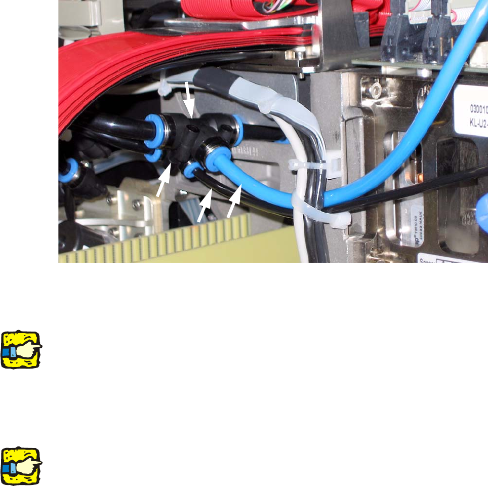
Fig. 2.7.1 Initial State of the piping
: Vacuum pipe: cut through the “Twin Head supply pipe” approx. 3 cm before the T-fitting (2).
: Remove the T with the hose connector
2
See also Fig. 2.7.5 !
2
: Air supply line: Replace the T-fitting (3) by the T-fitting (2) with the 3cm hose.
: Push the T-fitting (3) onto the hose connector of the combination.
: Put “Twin Head supply tube“(1) into the T-fitting (3).
2
The thin black hose (4) supplies "Twin Head return unit“.
2
1
3
2
4