00195372-0102_AI_Vakuumpumpe_D1D2_DE EN - 第37页
D1 / D2 2 Assembly instructions for vacuum pump 11/2006 Edition 37 : Put the tube (4) to the back of the T -fitting (3). The tube layout should af terwards look as shown in Fig. 2.7.4 and/or Fig. 2.7.5. : Remove the loos…
2 Assembly instructions for vacuum pump D1 / D2
11/2006 Edition
36
2.7 Modifying the piping
1 pc Anschluss-Kit für Köpfe D1 03053075-xx 2
bestehend aus: 2
1 Schlauch Vakuum 03053080-xx 2
0.05 M Pneumatikschlauch PUN 6 2
1 T-fitting QST-6 00320170-xx 2
1 Stopfen QSC-6H 2
1 Entriegelungswerkzeug für Q8 03047090-xx 2
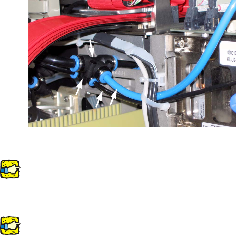
Fig. 2.7.1 Initial State of the piping
: Vacuum pipe: cut through the “Twin Head supply pipe” approx. 3 cm before the T-fitting (2).
: Remove the T with the hose connector
2
See also Fig. 2.7.5 !
2
: Air supply line: Replace the T-fitting (3) by the T-fitting (2) with the 3cm hose.
: Push the T-fitting (3) onto the hose connector of the combination.
: Put “Twin Head supply tube“(1) into the T-fitting (3).
2
The thin black hose (4) supplies "Twin Head return unit“.
2
1
3
2
4
D1 / D2 2 Assembly instructions for vacuum pump
11/2006 Edition
37
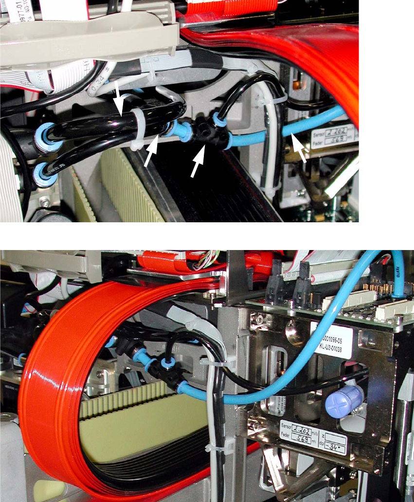
: Put the tube (4) to the back of the T-fitting (3). The tube layout should afterwards look as shown
in Fig. 2.7.4 and/or Fig. 2.7.5.
: Remove the loose tube from the C&P placement head.
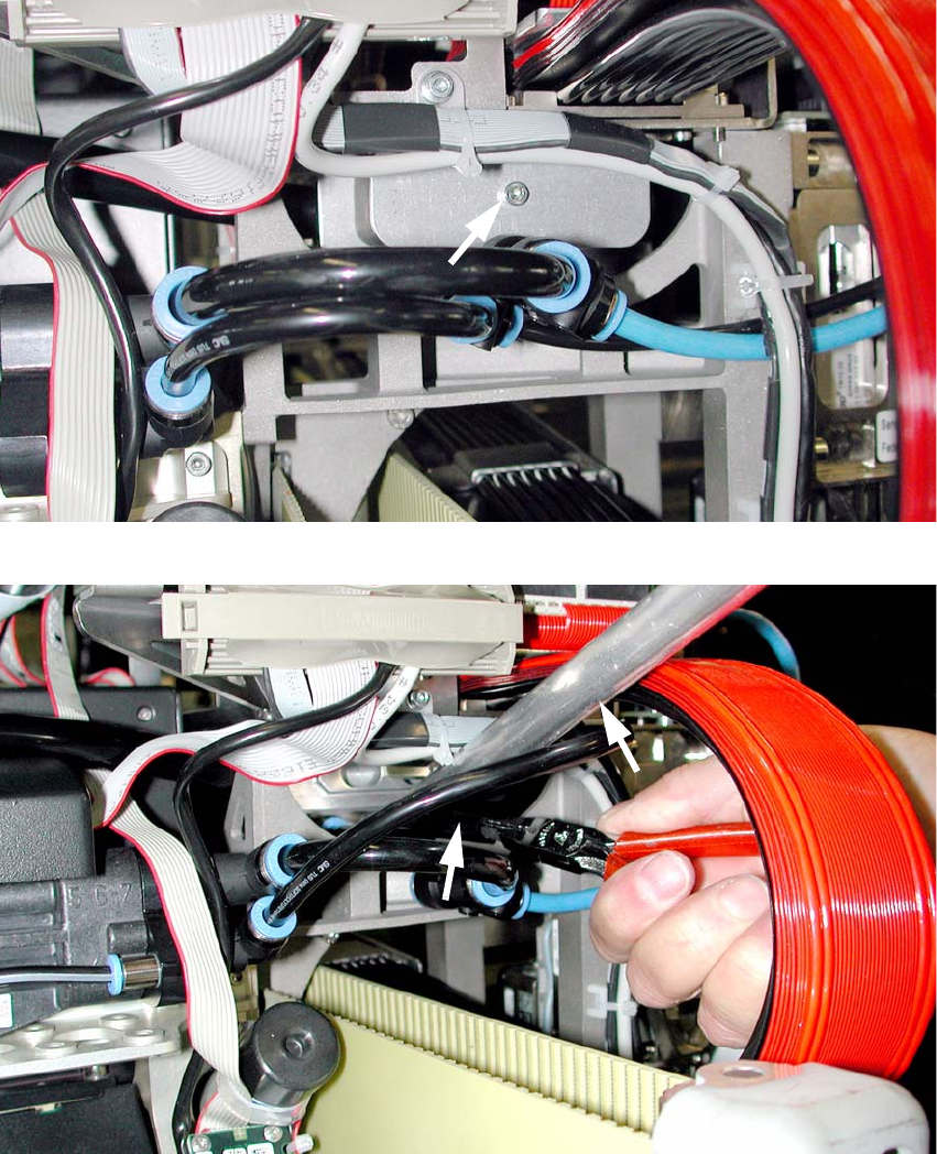
: Detach the cover from compressed air distributor and remove the muffler (So that you have
space for the unblocking tool).
Fig. 2.7.2 Cover with a rear muffler
Fig. 2.7.3 Remove the tube from the compressed air distributor
2 Assembly instructions for vacuum pump D1 / D2
11/2006 Edition
38
: Press with the unblocking tool on the hose coupling and pull the vacuum tubing out with pliers.
: Push the provided hose (4 in Fig. 2.7.4) into the compressed air distributor and connect it with
the C&P placement head.
: Replace the muffler into the compressed air distributor and bolt you on the cover.
Fig. 2.7.4 Pipe connection reequipped for C&P and Twin head
Fig. 2.7.5 Ppipe connection fixed
2
3
2
4
1