00195372-0102_AI_Vakuumpumpe_D1D2_DE EN - 第45页
D1 / D2 2 Assembly instructions for vacuum pump 11/2006 Edition 45 : Note the measured value. : Remove the measuring tube from the vacuum distribution block and put the plugs back in. : Close all doors. : Repeat the abov…
2 Assembly instructions for vacuum pump D1 / D2
11/2006 Edition
44
2.9.2.2 Measure the vacuum with an external pressure measurement instrument:
– at the measuring connection of the vacuum distribution blocks entrance (see Fig. 2.9.4) and
afterwards
– at an open nozzle in the holding circuit of the placement head (see Fig. 2.9.5). All other
nozzles must be closed.
Pressure may amount to max. 20-30 mbar! Otherwise everything is not sealed. 2
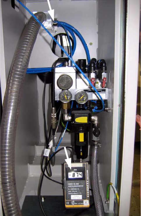
Fig. 2.9.4 Measurement of the vacuum distribution block (machine entrance)
: Remove for the plugs from the measuring connection at the vacuum distribution block.
: Attach the external measuring instrument.
: Switch the vacuum pump on.
: Open if necessary the inserted vacuum shut-off valves
: Open the compressed air shut-off valves.
: Switch the main switch on.
D1 / D2 2 Assembly instructions for vacuum pump
11/2006 Edition
45
: Note the measured value.
: Remove the measuring tube from the vacuum distribution block and put the plugs back in.
: Close all doors.
: Repeat the above with all attached mounting machines.
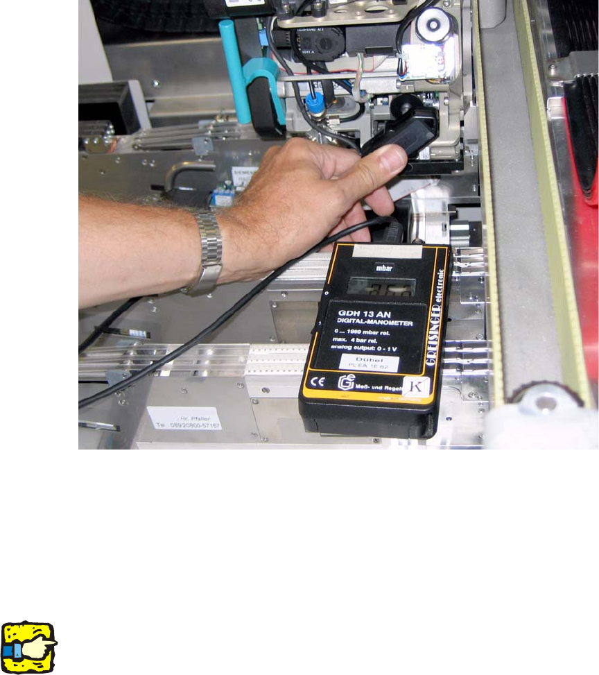
Fig. 2.9.5 Measuring a nozzle
: Press the gauge connecting piece of the external measuring instrument to the open nozzle.
If the values specified above are not reached, the cause
usually lies in a not correctly suspended
tube in the head area. Proceed as follows: 2
: Press all hoses down with
pliers.
: Repeat the vacuum measurement.
2
With closed nozzles with attached vacuum pump the vacuum is usually approx. 30-50 mbar
lower in the holding circuit than at a Venturi producer in the pickup circuit (in each case mea-
sured with external measuring instruments at an (open
) pipette in the pickup circuit and one (open)
in the holding circuit). 2
This difference can be accepted, if with 521 m NN (a
ltitude Munich, Start-up SIPLACE ) a value
800 mbar of at least is reached. 2
2 Assembly instructions for vacuum pump D1 / D2
11/2006 Edition
46
2.9.2.3 Checking the holding circuit of the vacuum system
The flow can be controlled “indirectly “over the vacuum characteristic. 2
Proceed as follows: 2
: Re
move the nozzles from the placement head (in order to allow maximum flow.
: Ope
n sequentially in the SITEST the segment in fetching position and turn it by means of as-
terisking into the holding circuit.
The vacuum measurement in the holding circuit sh
ows
with every additionally opened nozzle a
vacuum waste of approx. 60-90 mbar. 2
2
With six opened nozzles the vacuum could for example drop from -880 mbar to -520 mbar.
With six C&P heads on two mounting machines with a common vacuum pump, the decrease of
pressu
re is larger; with only one placement machine smaller (four or two C&P heads). 2
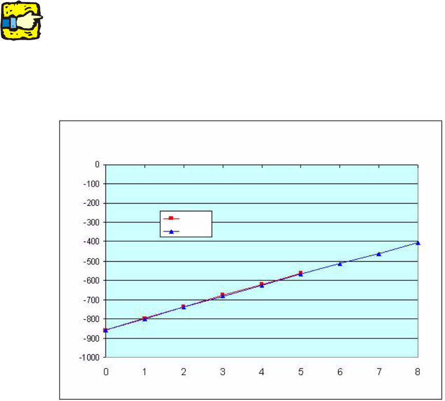
2.9.2.4 Vacuum Characteristics
The following diagrams also apply to the D1 and D2 (provided with other mounting equipment) 2
Fig. 2.9.6 C&P6 (red) and C&P12 (blue): Pressure drop at 1, 2, 3... open nozzles
Vacuum [mbar]
Number of open nozzles
Gantry 1
Gantry 2
Vacuum curve for S27HM with ELMO 2BL 1 1000 vacuum pump and 720 nozzles
Gantry 1: 6-segment head / Gantry 2: 12-segment head