P-261-004e.pdf - 第5页
MODEL DL-G100 0612-001 目 次 CONTENTS デュアル搬送対応 DL-G100 For Dual T ransfer DL-G100 Fig. NL 供給コンベア INPUT CONVEYOR Fig. NL-1 ベース部 Base Section Fig. NL-2 シュート Chute Fig. NL-3 搬送部(手前) T ransfer Section(Front) Fig. NL-4 搬送部(奥) T…
MODEL DL-G100
1012-004
2
USING YOUR EXPLODED ILLUSTRATION
This Exploded Illustration shows the information about the parts of " For Dual Transfer
DL-G100 " for GXH Series and is made for Parts Ordering.
You must not replace a part with a new one according to only the information of this
Exploded Illustration.
1. Inquiring
For identification of each part, numbers are placed on illustration pages. These
numbers (Key No.) again appear in the far left column of the part table joined up
with the illustration.
The number shown in the Q’ty column of the part table represents the quantity of
certain part used in the equipment. In case of unit assembly, however, the number
represents the quantity of certain part contained in single unit.
2. Parts Ordering
For ordering parts, some parts might not be supplied as a single item, due to the
constitution of such parts.
When ordering parts, be sure to inform us of the following details:
Model Type
Serial No.
Fig. No.
Key No.
PART No.
PART NAME
Quantity
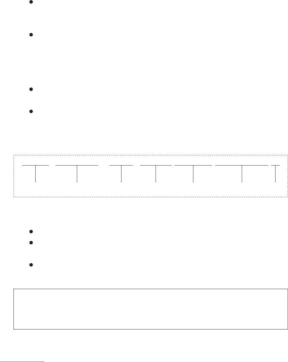
[Example]
3. Miscellaneous
This Exploded Illustration is subject to change without prior notice.
All rights reserved. No part of this work covered by the copyrights hereon may be
reproduced or copied without written permission of the publisher.
'' NOTE '' is used to show the notice that is not directly related to safety.
Some of the parts shown in the Exploded Illustration could fall into the scope of your
government’s regulations on strategic products. In that case, anybody who intend to
export the product should acquire due authorization.
DL-G100
Model Type
123456S 7890
Serial No.
Key No.210
Key No.
6301237145
PART No.
Q'ty
1
Fig. No.
Fig. NL-3
PART NAME
SENSOR,PELEC

MODEL DL-G100
0612-001
目 次
CONTENTS
デュアル搬送対応
DL-G100 For Dual Transfer DL-G100
Fig. NL
供給コンベア
INPUT
CONVEYOR
Fig. NL-1
ベース部
Base Section
Fig. NL-2
シュート
Chute
Fig. NL-3
搬送部(手前)
T
ransfer Section(Front)
Fig. NL-4
搬送部(奥)
Transfer Section(Rear)
Fig. NA
バックアップ部1
BACK UP SECTION 1
Fig. NA-1
ベース部
Base Section
Fig. NA-2
バックアップテーブル
Back Up
T
able
Fig. NA-3
シュート駆動部
L Chute Driving Section L
Fig. NA-4
シュート駆動部
R Chute Driving Section R
Fig. NA-5
シュート1
,
3
Chute 1,
3
Fig. NA-6
シュート2
,
4
Chute 2,4
Fig. NA-7
搬送部(手前)
T
ransfer Section(Front)
Fig. NA-8
搬送部(奥)
Transfer Section(Rear)
Fig. NB
バッファ部
BUFFER SECTIO
N
Fig. NB-1
ベース部
Base Section
Fig. NB-2
シュート
Chute
Fig. NB-3
搬送部(手前)
T
ransfer Section(Front)
Fig. NB-4
搬送部(奥)
Transfer Section(Rear)
Fig. NC
バックアップ部2
BACK UP SECTION 2
Fig. NC-1
ベース部
Base Section
Fig. NC-2
バックアップテーブル
Back Up
Table
Fig. NC-3
シュート駆動部
L Chute Driving Section L
Fig. NC-4
シュート駆動部
R Chute Driving Section R
Fig. NC-5
シュート1
,
3
Chute 1,
3
Fig. NC-6
シュート2
,
4
Chute 2,4
Fig. NC-7
搬送部(手前)
Transfer Section(Front)
Fig. NC-8
搬送部(奥)
Transfer Section(Rear)
Fig. NR
排出コンベア
OUTPUT CONVEYOR
Fig. NR-1
ベース部
Base Section
Fig. NR-2
シュート
Chute
Fig. NR-3
搬送部(手前)
T
ransfer Section(Front)
Fig. NR-4
搬送部(奥)
Transfer Section(Rear)
Fig. ND
ケーブル
CABLE
Fig. ND-1
供給コンベア
Input Conveyor
Fig. ND-2
バックアップ部1
Back Up Section 1
Fig. ND-3
バッファ部
Buffer Section
Fig. ND-4
バックアップ部2
Back Up Section 2
Fig. ND-5
排出コンベア
Output Conveyor
3
CONT-1

MODEL DL-G100
0909-002
目 次
CONTENTS
デュアル搬送取付本体対応
G -S165-01 Main Machine Modification For
Attaching Dual Transfer G -S165-01
Fig. B-1
本体部
-
フレーム部
Main Body Section-Frame Section
Fig. G-4
カバー部
-
パネルフレーム
Cover Section-Panel Frame
Fig. BA-1
架台下
A-
電装パネル
Underframe
A-Electrical Panel
Fig. BA-2
架台下
A-
ケーブル
L Underframe
A-Cable L
Fig. BC-1
架台下
C-
電装パネル
Underframe C-Electrical Panel
Fig. BC-2
架台下
C-
ケーブル
R Underframe C-Cable R
Fig. BL-3
電装ボックス
L-
リレー2、
I/O
ボード
Electrical Box L-Relay 2,I/O Board
Fig. BL-4
電装ボックス
L-DC
電源2
Electrical Box L-DC Power Supply 2
Fig. BL-7
電装ボックス
L-
コンベアドライバ
Electrical Box L-Conveyor Driver
Fig. BR-3
電装ボックス
R-
リレー2、
I/O
ボード
Electrical Box R-Relay 2,I/O Board
Fig. BR-7
電装ボックス
R-
コンベアドライバ
Electrical Box R-Conveyor Driver
Fig. D-4
部品認識部
-
ケーブル
Recognition Section-Cable
Fig. FB-2
制御
PC
部
-
ケーブル
Control PC Section-Cable
4
CONT-2