FCM_User Reference Manual.pdf.pdf - 第120页
MIS User Re ference Manual 4022 5 91 96082 5-28 F CM Mult ifl ex 02.02 ✱✱ Detailed Infor mation ▼ Dis played Info rmatio n The [Pr ocess g r aph. ..] rep o rt g ive s a gra ph ical overvie w of the p ro cess er r ors . T…
4022 591 96082 User Reference Manual
02.02 FCM Multiflex 5-27
MIS
5.3.2.5 [Reports] > [Process graph...]
TABLE 5-12 Quick Reference
fcm0527a.tif
SCREEN 5-22 [Process graph...] screen example
Actions ■ select [Functions...] in the MIS pull-down menu
■ select [Reports]
■ select [Process graph...]
Conditions ■ order active
Information ■ number of auto retries per placement module + per
feeder
■ number of manual retries per placement module +
per feeder
■ number of placed SMDs per placement module + per
feeder
■ number of not placed SMDs (skipped) per placement
module + per feeder
■ misalign details per placement module + per feeder
Display Options ■ process graph for all modules
• averages = errors per placement module
• details = errors per feeder
■ process graph per placement module (zoom-in
function)
• all errors
• misalign errors
■ errors in PPMs or absolute
MIS
User Reference Manual 4022 591 96082
5-28 FCM Multiflex 02.02
✱✱Detailed Information
▼ Displayed Information
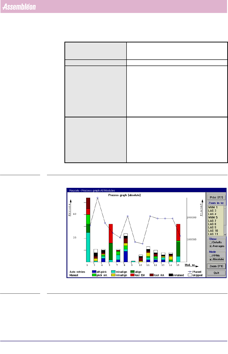
The [Process graph...] report gives a graphical overview of the process errors.
They can either be displayed for all placement modules or for a specific
placement module.
■ The process errors are displayed in bar-graphs, that have different colours for
each process error type. The amount of errors can be read from the left Y-axis.
This can either be in absolute numbers or in PPMs, depending on the selected
mode.
■ The number of placed SMDs are displayed in a line-graph. The amount
ofplaced SMDs can be read from the right Y-axis.
■ The placement module position or the feeder position can be read from the
X-axis, depending on the selected mode.
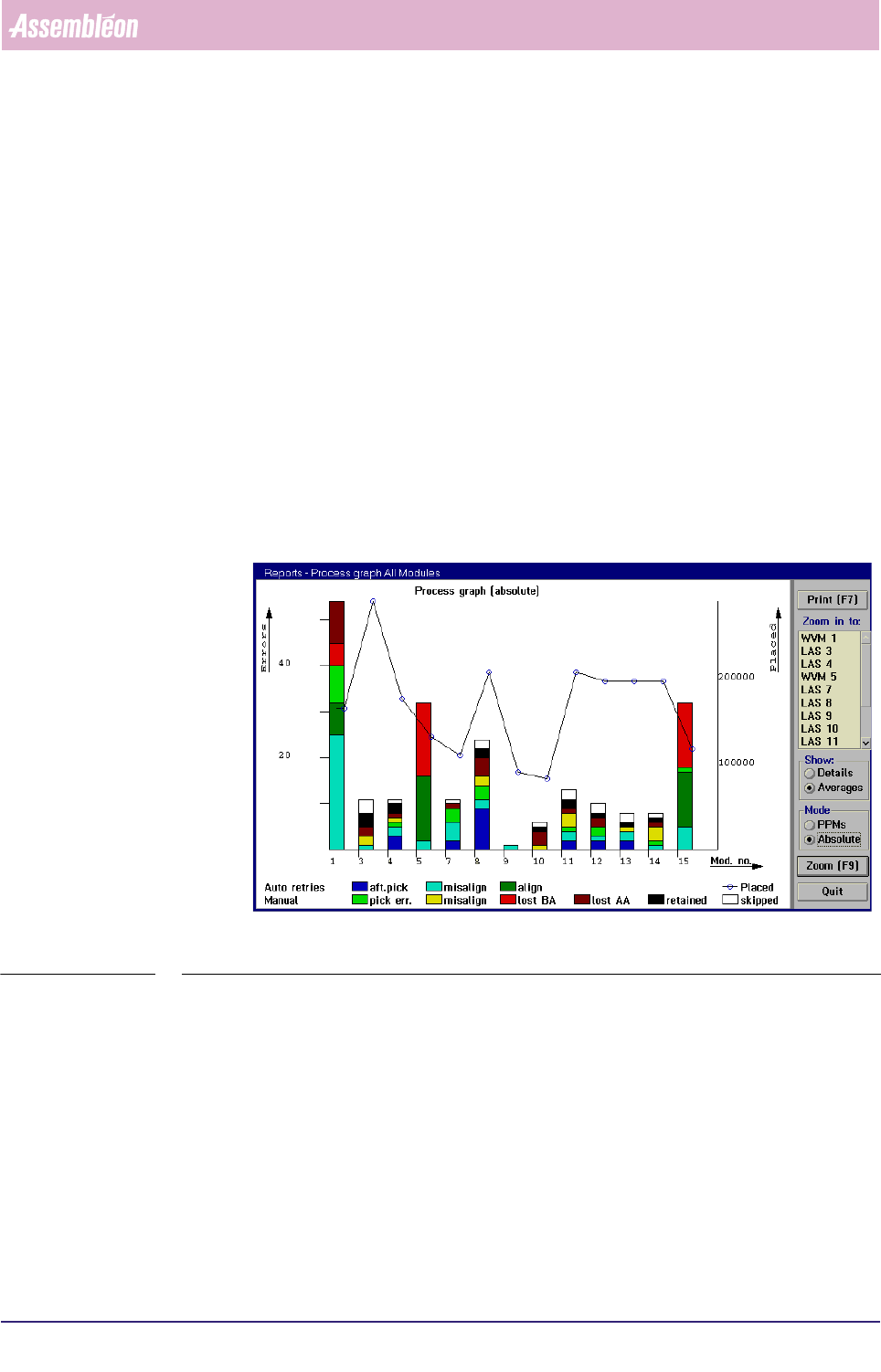
On first entry, the report displays an overview on all (used) placement modules (see
SCREEN 5-23).
fcm0527a.tif
SCREEN 5-23 [Process graph...] All modules screen example
4022 591 96082 User Reference Manual
02.02 FCM Multiflex 5-29
MIS
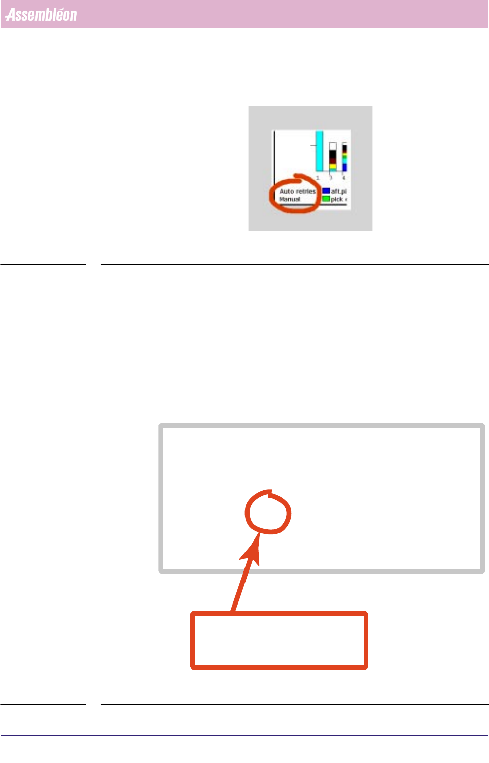
■ The process errors are divided into auto retries and manual retries (see below).
fcm0528a.tif
SCREEN 5-24
• An auto retry is a retry without operator intervention (automatic); the
maximum allowed number of auto retries is determined in the action spec,
(see SCREEN 5-25).
• A manual retry is a retry by operator intervention. After the FCM Multiflex
has reached the auto retry number limit, it stops, and manual retries may be
done by the operator then. Note that only those manual retries are taken
into account for the
[Process report...] report that were successful at first
attempt.
fcm0517a.eps
SCREEN 5-25 Action spec setting of the maximum number of auto pick retries (refires)
FEEDER 1 1 T8-M/4 T 333-222-112 SOD-80
COMMENT index coordinates are relative to pipette origin
COMMENT indx/brd /refholex/refholey/board_x /board_y
INDEX 1 3 -75.500 294.250 -81.500 138.000
INDEX 1 4 74.500 294.250 68.500 138.000
INDEX 2 3 4.500 294.250 -1.500 138.000
COMMENT pick coordinates are relative to pipette origin
COMMENT fd/pk/psh/rfr/pick_x /pick_y /pick_phi/na/prf/arf/ale/ple
PICK 1 1 1 2 19.000 77.000 90.0 1 75 55 80 80
COMMENT: In case a deviating dump position is needed enter
COMMENT: DUMP position_x position_y
COMMENT mount coordinates are in board coordinates
in this example, the number of auto(matic)
pick retries (or
refires
) is set to 2
rfr = refires