FCM_User Reference Manual.pdf.pdf - 第133页
4022 591 96082 User Re ference Manual 02.02 FCM Multiflex 5-41 MIS ■ sel ect [P ri nt (F 7) ] or pr ess <F7> to pr in t t he g ra ph ■ sel ect [Al l] in ord er to go bac k t o th e o ver all pr oc ess r e p ort ■ s…
MIS
User Reference Manual 4022 591 96082
5-40 FCM Multiflex 02.02
▼ Controls
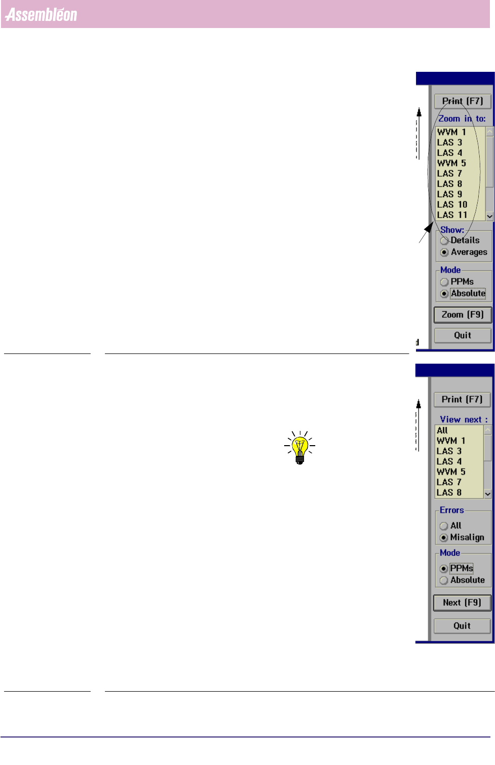
The controls on the right of the [Process graph...] screen
have the following functions:
■ select
[Print (F7)] or press <F7> to print the report
■ select [Averages] in the [Show] field to display the process
errors per placement module
■ select
[Details] in the [Show] field to display the process
errors per feeder position
■ select [PPMs] if you wish to display them in Parts Per Million
■ select [Absolute] if you wish to display the absolute number
of errors
■ to take a closer look to a specific placement module, select
a LAS/WVM placement module from the listbox
select
[Zoom (F9)] or press <F9>
This will display the process report of the selected LAS/WVM, in
which all process information is shown for each feeder position.
SCREEN 5-31
■ select
[All] in the [Errors] field if you wish to display all
process errors of the selected placement module
■ select
[Misalign] if you wish to take a closer look at the error
cause of misalign errors
NOTE: As LAS placement modules and WVM placement modules
have different alignment mechanisms, the error screens
will also display different alignment parameters (see
SCREEN 5-33 and SCREEN 5-34).
■ to switch to the process graph of another LAS/WVM module,
• either select [Next (F9)] or press <F9>
This will display the process graph of the placement
module that was marked in the listbox before. Each time a
[Next (F9)] command is given (or <F9> is pressed, next
item from the listbox will be marked.
• or directly select the placement module you want from the
listbox and then select
[Next (F9)] or press <F9> to display
its process graph
fcm0541a.tif
SCREEN 5-32
4022 591 96082 User Reference Manual
02.02 FCM Multiflex 5-41
MIS
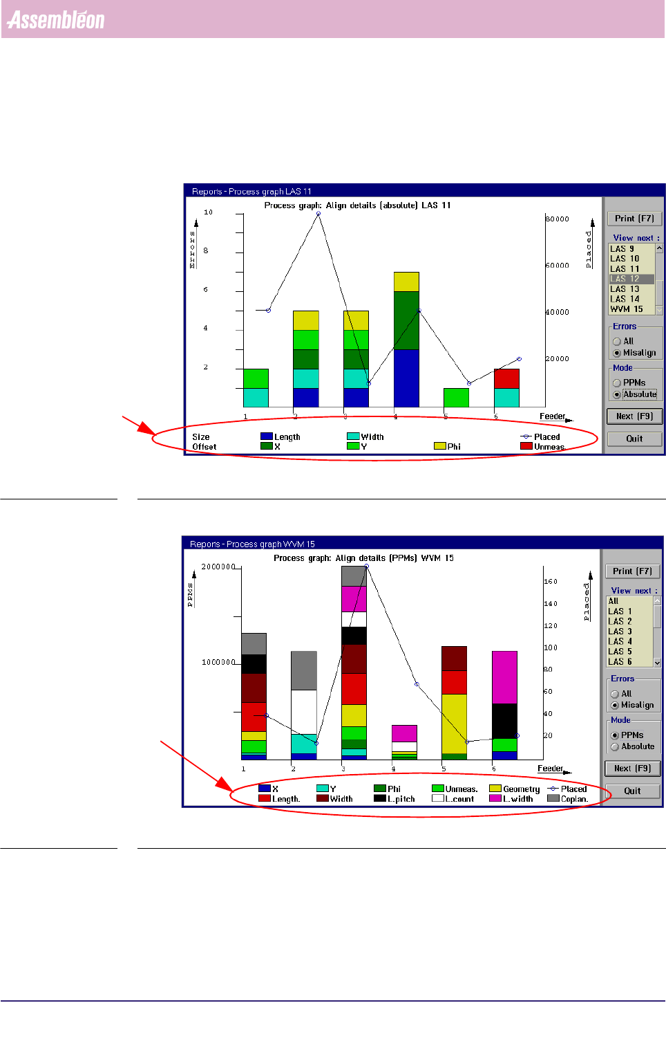
■ select [Print (F7)] or press <F7> to print the graph
■ select
[All] in order to go back to the overall process report
■ select [Quit] to leave the [Process graph...] menu
fcm0542a.tif
SCREEN 5-33 [Process graph...] LAS module misalign errors screen example
fcm0537a.tif
SCREEN 5-34 [Process graph...] WVM module misalign errors screen example
LAS specific align parameters
WVM specific align parameters

MIS
User Reference Manual 4022 591 96082
5-42 FCM Multiflex 02.02
5.3.2.6 SMD Counting, General Remarks
Looking at the MIS process reports and process graphs, you will notice that there
are inconsistencies within the SMD counting.
To have the MIS data interpreted correctly, please take following restrictions into
account.
■ During alignment of one SMD, more than one failure type may occur.
For instance, - in the case of a LAS placement module - a misalign error on both
[Length] and [Width] may occur.
Thus, the sum of the detailed misalignments does not always equal the sum
of the pick retries.
■ As dumped SMDs on LAS placement modules are not counted, a discrepancy
between [Picked], [Placed] and [errors] exists. Normally, pick and place actions
are completed, but not when the FCM Multiflex transport prevents LAS
placement modules to do so. In this case, on production restart the SMDs
involved are dumped without being counted.
■ When on error recovery a retry is issued and this retry fails,
[Auto retries] is
incremented, but
[Manual] is not.
■ Manual errors that occur on a production (re)start from the FCM Multiflex’s
[Stopped] status, by pressing <F5> and again <F5>, are not counted. Only once
the FCM Multiflex status is [Running] or [Waiting]1 , these errors are counted.
■ Manual errors are updated in MIS only if the error has been solved. So, if the
recovery action of a manual error is
[Skip Board] or [Skip Action], this error is
not counted.
■ The
[Auto retries] data are only updated on a MIS data collection action.