FCM_User Reference Manual.pdf.pdf - 第139页
4022 591 96082 User Re ference Manual 02.02 FCM Multiflex 5-47 MIS 5.3.4 Troub leshooti ng 5.3.4.1 [Tr ou bleshooti ng] > [T race component ...] T ABL E 5-22 Qui ck Refer ence fcm05 45a.tif SCREE N 5-3 6 [Trace com po…
MIS
User Reference Manual 4022 591 96082
5-46 FCM Multiflex 02.02
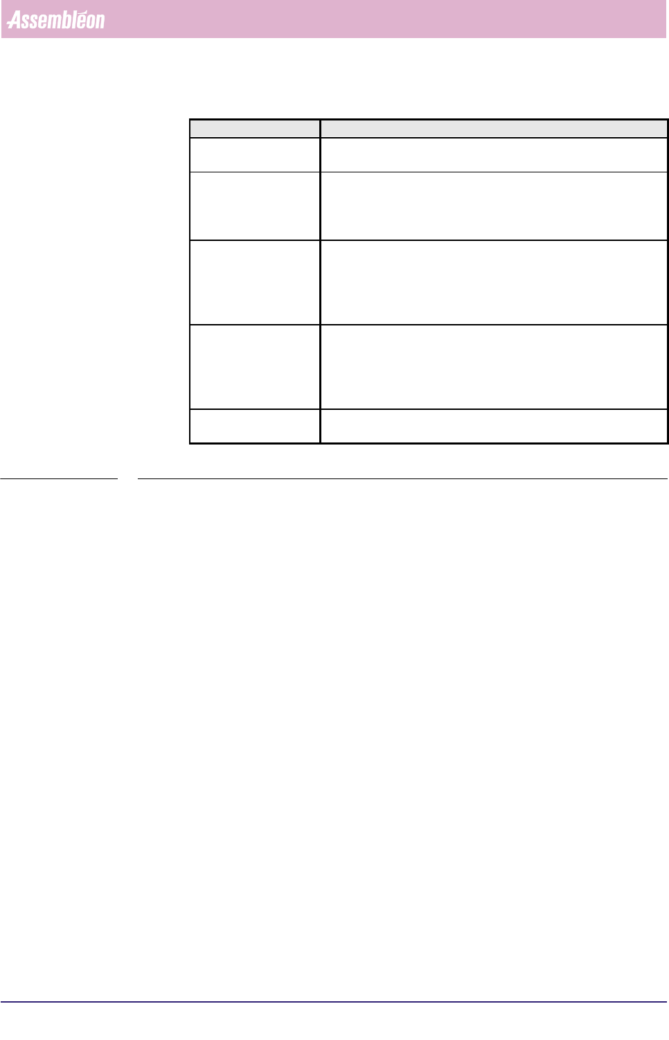
TABLE 5-21
▼ Controls
The controls on the right of the screen (see SCREEN 5-35) have the functions:
■ select
[Print (F7)] or press <F7> to print the report
■ select
[Quit] to leave the [Production times...] menu
Report text Explanation
Nr of processed
boards
the total number of processed boards, which means the good + the
skipped + the suspected boards all together
Nr of empty produc-
tion cycles (no board)
■ the number of production cycles in which no boards were
loaded in the FCM Multiflex (all transport carriers empty)
■ this is an indication of how (in)efficient your FCM Multiflex
worked
Average cycle time
during production
■ the average production cycle time per board calculated for the
production running time
■ this is:
production running time
number of processed boards number of empty production cycles
Average cycle time
during current order
■ the average production cycle time per board calculated for the
total elapsed time
■ this is:
total elapsed time
number of processed boards number of empty production cycles
Number of SMD’s
mounted
total number of all SMDs that had been placed on the boards so far
during the current MIS period
4022 591 96082 User Reference Manual
02.02 FCM Multiflex 5-47
MIS
5.3.4 Troubleshooting
5.3.4.1 [Troubleshooting] > [Trace component...]
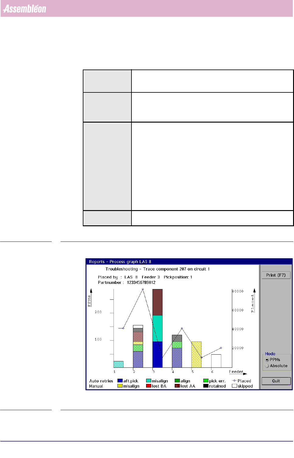
TABLE 5-22 Quick Reference
fcm0545a.tif
SCREEN 5-36 [Trace component...] process graph screen example
Actions ■ select [Functions...] in the MIS pull-down menu
■ select [Troubleshooting]
■ select [Trace component...]
Conditions ■ order active
■ item code of the badly placed SMDs must be known
■ in case of a multi-circuit board, the number of the board circuit on
which the problem exists must be known
Information following information will be given on the error environment:
■ the relevant placement module number
■ the relevant feeder position
■ the relevant pick position
■ the SMD reel’s partnumber used for the concerned SMDs
■ the number of auto retries
■ the number of manual retries
■ the number of placed SMDs
■ the number of not placed SMDs (skipped)
the occurred process errors on the traced SMD will be displayed in
bright colours, whereas the other errors are displayed in pale colours
Display Options ■ absolute error numbers
■ errors in Parts Per Millions (PPMs)
MIS
User Reference Manual 4022 591 96082
5-48 FCM Multiflex 02.02
✱✱Detailed Information
When bad placements have been found on visual board inspection, it is quite time
consuming to trace the badly placed SMDs back to the placement module(s) and
feeder(s) from which they originated. Especially if a lot of SMDs have been placed
on a board, and you need to search through the complete action spec.
By means of the SMD’s item code and the circuit number (as both used in the
action spec), the
[Trace component...] function gives you the possibility to easily
trace the errors back to the machine parts involved.
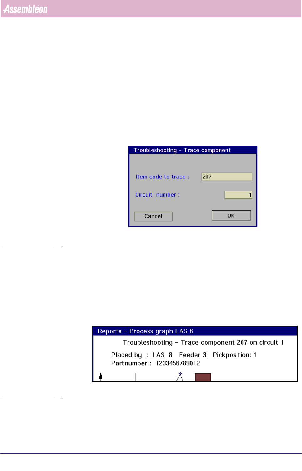
▼Displayed Information
On selecting the [Trace component...] command, the following dialogue screen will
appear:
fcm0546a.tif
SCREEN 5-37
Once the item code and circuit number have been entered, the MIS system will
start searching for the SMD in the action spec.
If the entered SMD parameters are found, the process graph of the placement
module where this SMD is used will be displayed (see SCREEN 5-41).
■ On top of the graph, first the input information is shown:
• the component (SMD) number to be traced
• the concerned circuit number
fcm0547a.tif
SCREEN 5-38
■ Next, the output information is given:
• the placement module, the feeder, and the pick position where the
selected SMD type has been processed