FCM_User Reference Manual.pdf.pdf - 第149页
4022 591 96082 User Re ference Manual 02.02 FCM Multiflex 5-57 MIS 5.3.5.2 [Report s] > [Ser v o diagnost ic. ..] T ABL E 5-26 Qui ck Refer ence fcm05 55a.tif SCREE N 5-47 Example of a [Servo d i agnostic ...] gra ph …
MIS
User Reference Manual 4022 591 96082
5-56 FCM Multiflex 02.02
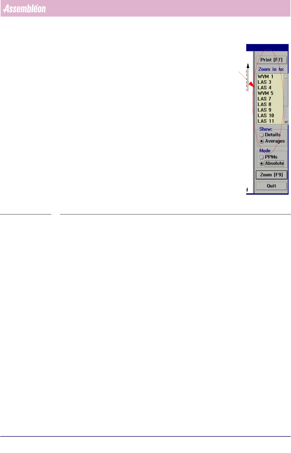
▼Controls
The controls on the right of the [Machine performance...] screen
have the following functions:
■ select
[Print (F7)] or press <F7> to print the report
■ select one of the FCM Multiflex modules from the listbox to
have its report shown on the screen
■ select
[Next (F9)] to press <F9> to show next module from the
listbox
■ select
[Quit] to leave the [Machine performance...] menu
fcm0554a.tif
SCREEN 5-46
4022 591 96082 User Reference Manual
02.02 FCM Multiflex 5-57
MIS
5.3.5.2 [Reports] > [Servo diagnostic...]
TABLE 5-26 Quick Reference
fcm0555a.tif
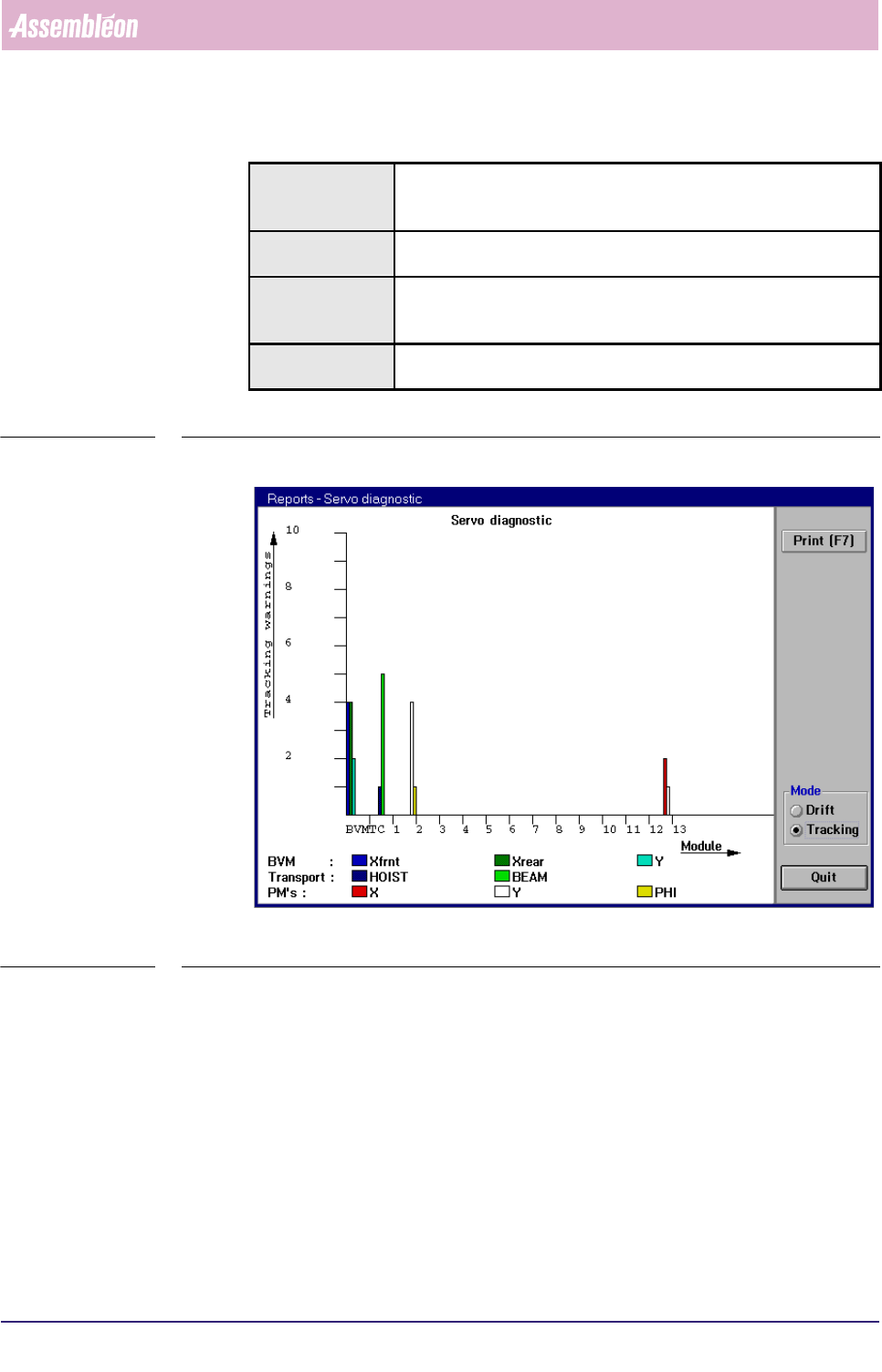
SCREEN 5-47 Example of a [Servo diagnostic...] graph in [Tracking] mode
✱✱Detailed Information
▼Displayed Information
The [Servo diagnostic...] graph gives a graphical overview of all tracking warnings
and drift that occurred on the various FCM Multiflex modules.
A tracking warning is generated when the difference between aimed and achieved
motion (“slip”) of the servo system exceeded a fixed limit.
The drift is defined as the total number of servo increment pulses that did not
match the nominal value.
Actions ■ select [Functions...] in the MIS pull-down menu
■ select [Reports]
■ select [Machine performance...]
Conditions ■ supervisor access level
■ order active
Information ■ information on all servo systems by graphical display of
• the total number of tracking warnings per servo system
• the total drift that occurred per servo system
Display Options ■ display of tracking warnings
■ display of drift
MIS
User Reference Manual 4022 591 96082
5-58 FCM Multiflex 02.02
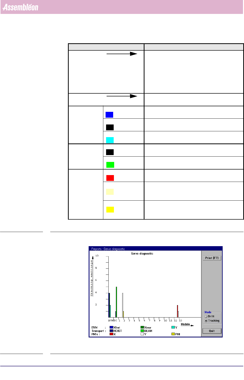
Graph explanation
TABLE 5-27
fcm055a.tif
SCREEN 5-48 Example of a [Servo diagnostic...] graph in [Tracking] mode
Graph legend Explanation
Tracking warnings scale for the total number of tracking warnings,
which can be defined as:
the number of times the difference between aimed
and achieved motion (“slip”) of the servo system
exceeded a fixed (warning) limit (in Tracking mode
only)
Module along this line the various used modules involved
are indicated
BVM Xfrnt the number of times a tracking warning occurred for
the BVM’s X-motor at the front side
Xrear the number of times a tracking warning occurred for
the BVM’s X-motor at the rear side
Y the number of times a tracking warning occurred for
the BVM’s Y-motor
Transport HOIST the number of times a tracking warning occurred for
the hoist motor of the transport beam
BEAM the number of times a tracking warning occurred for
the X-motor of the transport beam
PMs X the number of times a tracking warning occurred for
the X-motor of the indicated placement module
Y the number of times a tracking warning occurred for
the Y-motor of the indicated placement
module
PHI the number of times a tracking warning occurred for
the PHI-motor of the indicated placement
module