FCM_User Reference Manual.pdf.pdf - 第200页
Pr oduc t Ch ang e Ov er User Re f eren ce Manu al 4022 591 960 82 6-8 FCM M ultiflex 02.02 Calib ra tion di alog: Upper strip : … mm (S R ) The posi tion of th e upper strip wi th respect t o th e north ed ge o f the bo…
4022 591 96082 User Reference Manual
02.02 FCM Multiflex 6-7
Product Change Over
6.2.4 Adjusting the Tool for the Dual Strip and Small Boards in
Combination with the Carrier Kit.
The dual strip is a strip for small boards. To mount it on a board only the fixed slide
is used to put the dual strip on. Follow the standard procedure and instead of two
strips only the dual strip is used.
The combination Carrier kit and small production boards (87.0mm to 101.5mm in Y)
can cause interference of the calibration strips with the reference pin. Therefor the
rear (north) strip should be placed lower then 23mm from the rear edge. A default
value can be 52.5mm from the edge (checkbox “fixed alternatives” checked gives
automatically the right value).
The offline preparation tool has this value also:
Use the adjustable slide and the support slide as one slide: push the support slide
against the adjustable slide and move it as one slide to fit in the production board.
Put the calibration strip on the support slide instead of on the adjustable slide. The
strip is mounted 52.5 mm from the rear edge.
6.2.5 Calibrating with Alternative Strip Positions
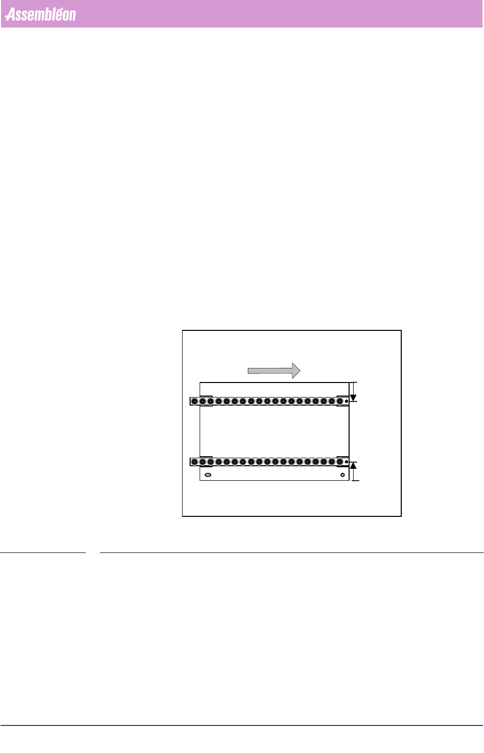
FIGURE 6-5
The FCM assumes that during Multiflex calibration the calibration strips are on
23mm from the edge of the board. If the strips are mounted on other positions
these positions must be mentioned to the FCM. This can be done in the “Cali-
bration” dialog.
Feeding direction into FCM
Top side
S
R
mm
S
F
mm
Front strip
Rear strip
South east
corner
Product Change Over
User Reference Manual 4022 591 96082
6-8 FCM Multiflex 02.02
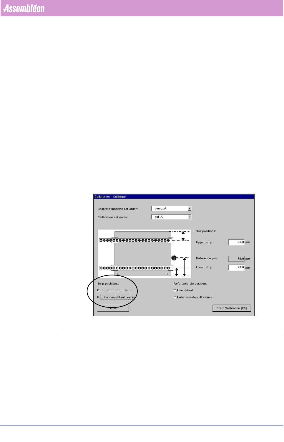
Calibration dialog:
Upper strip: … mm (S
R
)
The position of the upper strip with respect to the north edge of the board in mm is
displayed. These values can be edited by checking the checkboxes under ‘strip
position’. Default value: 23 mm
Lower strip: … mm (S
F
)
The position of the lower strip with respect to the south edge of the board in mm is
displayed. These values can be edited by checking the checkboxes under ‘strip
position’. Default value: 23 mm
Reference pin xx mm
For information about reference pin positions refer to 6.2.6
Strip positions checkboxes:
■ Use fixed alternatives. To use other defaults for the positions of the strips.
These values can be edited, refer to 6.2.7 for more details. If no suitable values
are found the default value is displayed: 23 mm
SCREEN 6-2
■ Enter non-default values. To enter strip positions (S
F
en S
R
). The text “Enter
strip positions” is displayed and entry fields with initial value 23mm are
displayed. In the entry fields new values can be entered. The strip position must
be measured from the edge of the board to the middle of the calibration strip in
millimeters.
Reference pin position checkboxes:
Refer to 6.2.6
4022 591 96082 User Reference Manual
02.02 FCM Multiflex 6-9
Product Change Over
6.2.6 Alternative Reference Pin Position
Multiflex calibration uses the reference pin (also known as temperature pin) in its
process. Therefor the FCM needs to know where this pin is located. In x-direction
the software can calculate (from board size and board pitch) the reference pin
position. However the y-position of the reference pin position is dependent of the
carrier type used.
IMPORTANT: In the action spec the correct values should be stated.
AS BVM
COMMENT RPX1 RPY1 RPX4 RPY4
SETUP REFERENCE_PINS 3.500 65.500 -236.500 65.500
TABLE 6-2
If the reference pin position in the action spec is incorrect or missing the correct
values can be entered in the “Calibration” screen. Entering the position via this
screen has the disadvantage that the value in the action spec is not updated. This
means that reuse of the action spec always requires calibration.
The calibration dialog:
The Y-postion of the reference pin w.r.t. the south edged of the board according to
the values in the action spec. These values can be edited by checking the
checkboxes under ‘reference pin position’. Default value: 36 mm.
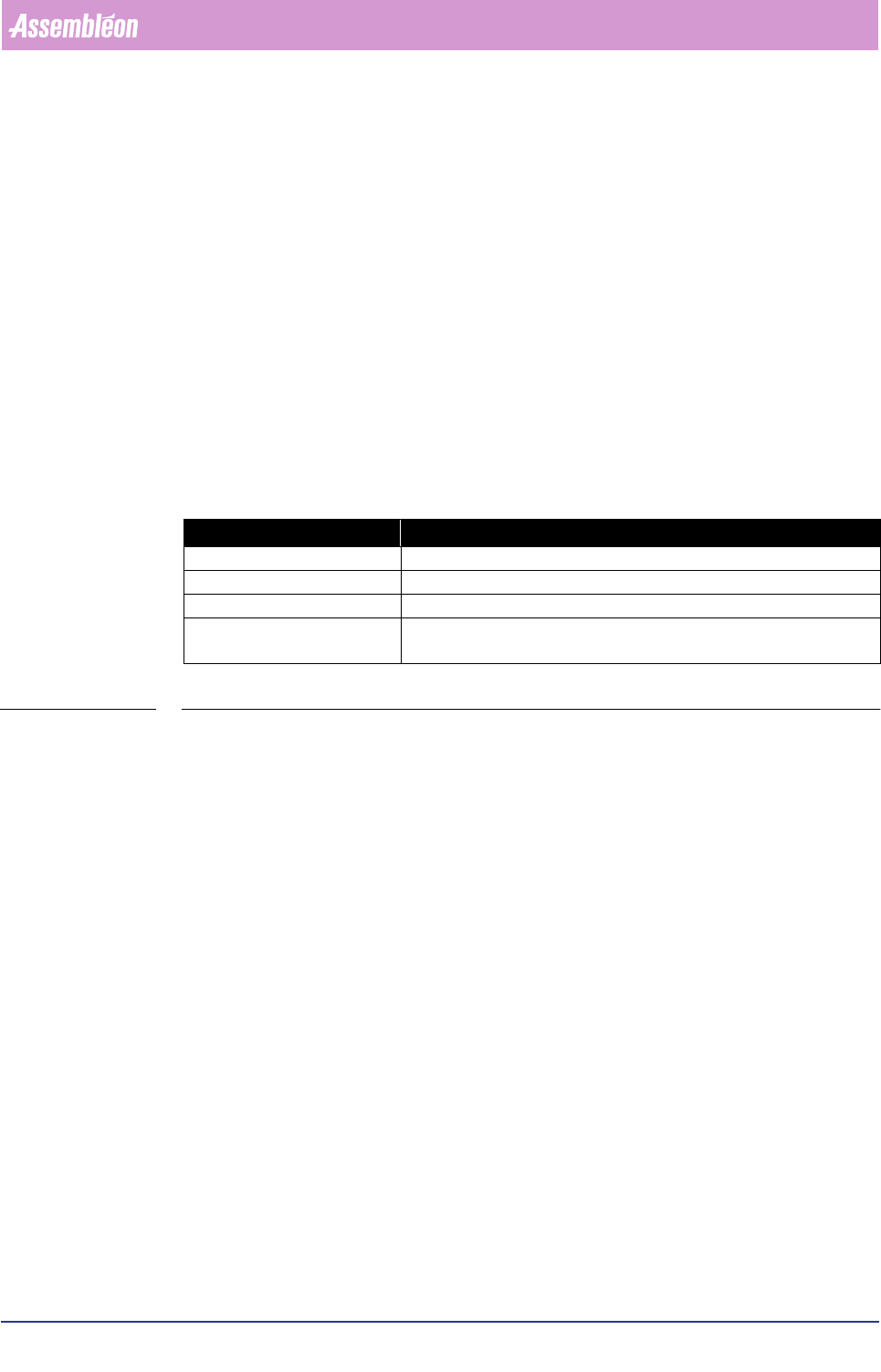
&DUULHUW\SH 5HIHUHQFHSLQ<SRVLWLRQ3PP
Multiflex board support 36 mm
Carrier kit 65 mm
Carrierset Check sticker on 1
st
carrier plate (Y position is needed)
Other Measure Y-position from front edge of the board to the middle of the
reference pin in millimeters