FCM_User Reference Manual.pdf.pdf - 第202页
Pr oduc t Ch ang e Ov er User Re f eren ce Manu al 4022 591 960 82 6-10 FCM M ult ifle x 02.02 R efer enc e pin pos ition ch eckbo x es: SCREEN 6-3 ■ Use d ef a ul t. T o use other d ef aults f or the posi tion of th e r…
4022 591 96082 User Reference Manual
02.02 FCM Multiflex 6-9
Product Change Over
6.2.6 Alternative Reference Pin Position
Multiflex calibration uses the reference pin (also known as temperature pin) in its
process. Therefor the FCM needs to know where this pin is located. In x-direction
the software can calculate (from board size and board pitch) the reference pin
position. However the y-position of the reference pin position is dependent of the
carrier type used.
IMPORTANT: In the action spec the correct values should be stated.
AS BVM
COMMENT RPX1 RPY1 RPX4 RPY4
SETUP REFERENCE_PINS 3.500 65.500 -236.500 65.500
TABLE 6-2
If the reference pin position in the action spec is incorrect or missing the correct
values can be entered in the “Calibration” screen. Entering the position via this
screen has the disadvantage that the value in the action spec is not updated. This
means that reuse of the action spec always requires calibration.
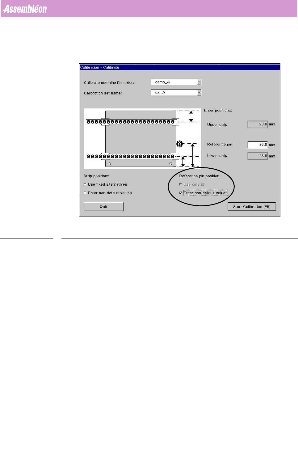
The calibration dialog:
The Y-postion of the reference pin w.r.t. the south edged of the board according to
the values in the action spec. These values can be edited by checking the
checkboxes under ‘reference pin position’. Default value: 36 mm.
&DUULHUW\SH 5HIHUHQFHSLQ<SRVLWLRQ3PP
Multiflex board support 36 mm
Carrier kit 65 mm
Carrierset Check sticker on 1
st
carrier plate (Y position is needed)
Other Measure Y-position from front edge of the board to the middle of the
reference pin in millimeters
Product Change Over
User Reference Manual 4022 591 96082
6-10 FCM Multiflex 02.02
Reference pin position checkboxes:
SCREEN 6-3
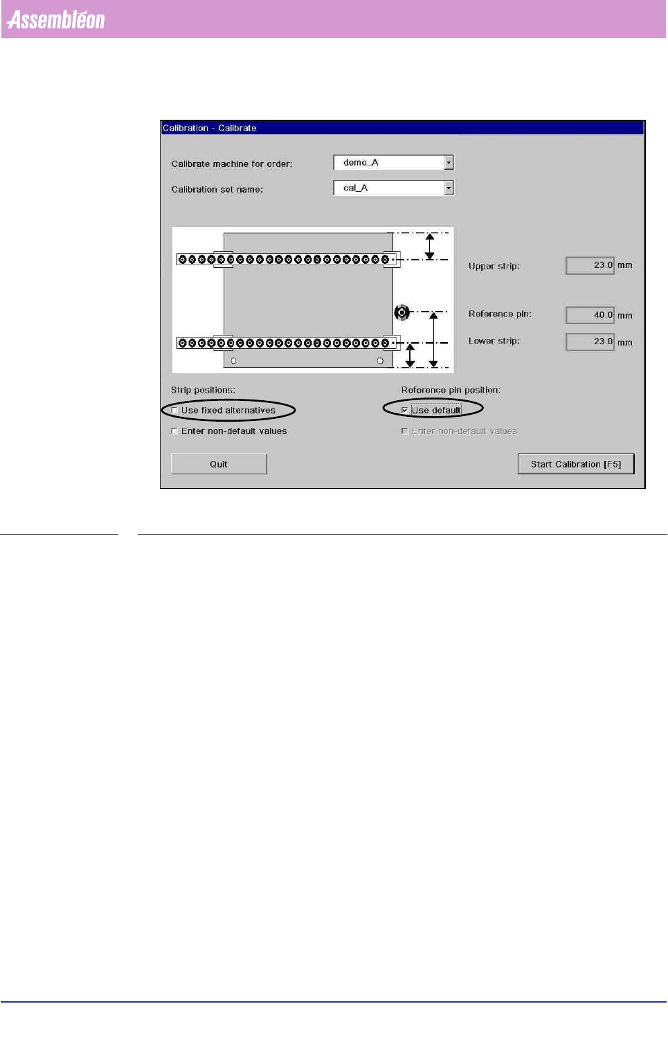
■ Use default. To use other defaults for the position of the reference pin. These
values can be edited, refer to 6.2.7 for more details. If there is no general
default specified in the file the default value of 36 mm is used.
■ Enter non-default values. To enter reference pin position. Entry fields with
initial value 36 mm are displayed. In the entry fields new values can be entered.
The reference pin position must be measured from the front edge of the board to
the middle of the reference pin in millimeters.
6.2.7 Making Customized Defaults for Calibration Strip Positions
and Reference Pin Positions
It is possible to create a default values for the calibration strip positions as well as
for the reference pin positions. This might be useful if frequently a carrier is used
that requires alternative strip positions or has a different reference pin position. In
the case of a different reference pin position it is recommended that the values in
the action spec are filled in correctly. If the values in the action spec are correct no
reference pin position has to be filled in during calibration because the action spec
value is used.
4022 591 96082 User Reference Manual
02.02 FCM Multiflex 6-11
Product Change Over
SCREEN 6-4
To set the default or fixed alternatives the following file has to be edited:
File: ..\SETUP\MCSTRIP.DAT
This file stores the parameters for strip and reference pin Y-positions during
Multiflex calibration is the checkbox “use default” or “use fixed alternatives” in the
dialog “Calibrate” are checked.
The file contents:
0 to5 lines “DEFAULT” <range><direction><offset_1><offset_2>
0 to 5 lines “REFPIN” <range><Y>
0 to 5 lines “STRIP” <range><direction><offset_1><offset_2>
<direction>::= “SS”|”NS”
■ “SS”: <delta_1> and <delta_2> are both offsets from the south (front) edge of
the board
■ “NS”: <delta_1> is from the north (rear) edge and <delta_2> is from the south
(front) edge