FCM_User Reference Manual.pdf.pdf - 第234页
Pr oduc t Ch ang e Ov er User Re f eren ce Manu al 4022 591 960 82 6-42 FCM M ult ifle x 02.02 SCREEN 6- 36 ■ T oggl e with <F5> between [Move] an d [Resize] as n ecessar y ■ P osition and r esize t he area of inte…
4022 591 96082 User Reference Manual
02.02 FCM Multiflex 6-41
Product Change Over
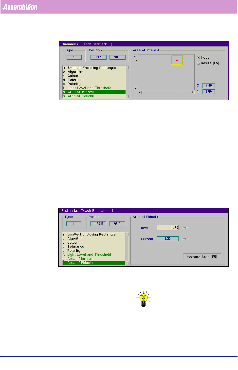
FIGURE 6-14 Area of interest for spot-type badmark detection
■ Toggle with
<F5> between [Move] and [Resize] as necessary
■ Position and resize the area of interest with the arrow keys or by means of the
tracker ball and the scroll bars
The X and Y value indicate the centre of the search area with respect to the centre
of the BVM camera.
For fiducial-type badmarks:
■ Select
[Area of Interest]
The [Area of Interest] determines where the system will look for the badmark.
In this way “confusing” elements - like certain print patterns - can be avoided.
NOTE: It is recommended to make the area of interest not larger then necessary,
for a large area of interest will increase the time required for a meas-
urement.
Product Change Over
User Reference Manual 4022 591 96082
6-42 FCM Multiflex 02.02
SCREEN 6-36
■ Toggle with
<F5> between [Move] and [Resize] as necessary
■ Position and resize the area of interest with the arrow keys or by means of the
tracker ball and the sliders
The X and Y value indicate the centre of the search area with respect to the centre
of the BVM camera.
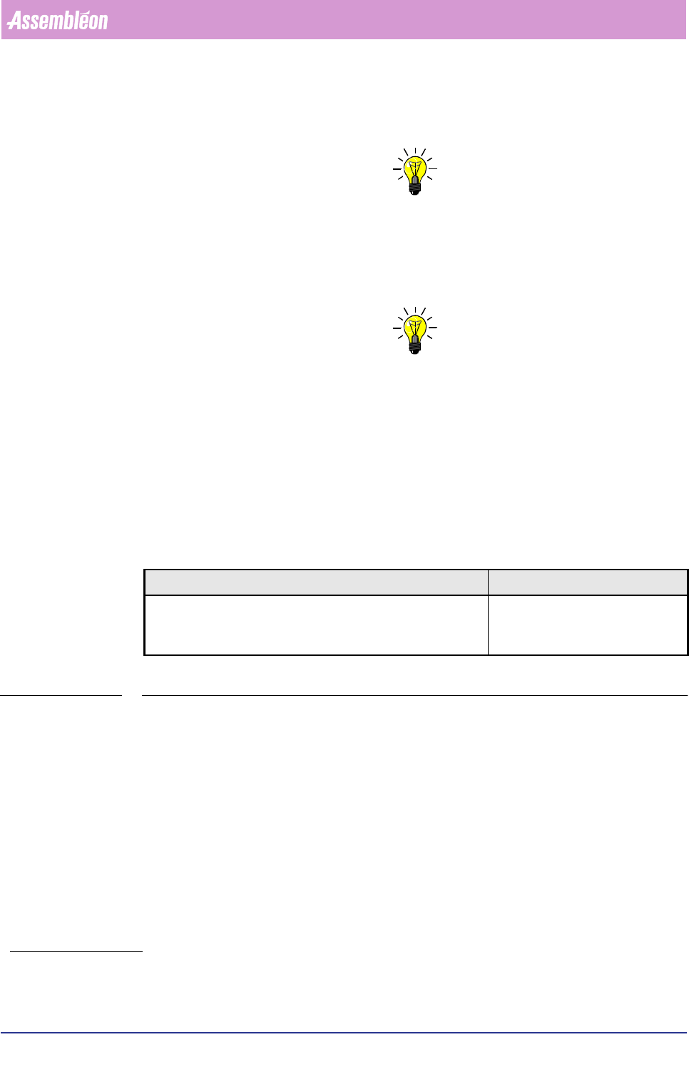
Area of Fiducial
Only relevant for fiducial-type badmarks using the binary algorithm.
■ Select
[Area of Fiducial]
This menu box gives the surface area of the badmark in mm
2
.
SCREEN 6-37
NOTE: For the parameters shown green in the list box, the settings can be taught
automatically by selecting >7HDFK@. The result of the automatic teaching
can be tested by selecting >0HDVXUH@.
■ Select [Teach]
■ Select [Measure]
4022 591 96082 User Reference Manual
02.02 FCM Multiflex 6-43
Product Change Over
The test results of the measurement will be shown in the [Status Badmark Meas-
urement]
box.
NOTE: Automatic teaching of a “ standard” badmark is only possible if both grey
levels (badmark and background) are visible in the [Area of Interest] (see
also the section Area of Interest). This implies that the camera must be
positioned slightly off-centre when the size of the badmark exceeds the
camera’s field of view.
NOTE: The automatic teach function of the badmark does not always supply
optimal results, especially for the grey level and threshold settings. If this
is the case, please refer to the section Light Level and Threshold for manual
teaching.
■ Select [Store] to store the taught data in the current data base
1
■ Select [Next Badmark] to go to the next badmark to be measured
■ Select
[Type...] to change the type of badmark to be taught
6.5.1.2 Measure Badmark
TABLE 6-14
■ Select [Measure Badmark...]
The badmark to be measured must be selected from the action spec, which lists all
used circuits and badmarks
1. Whenever a badmark with the identification
number of the taught badmark is selected in an
action spec, these stored settings will be used.
)XQFWLRQ $XWKRUL]DWLRQ
Check the results of a badmark measurement with the current
teach data.
- Operator
- Supervisor
- Maintenance/ Service Engineer