FCM_User Reference Manual.pdf.pdf - 第241页
4022 591 960 82 Us er Reference Man ual 02.02 FC M Multif lex 6-49 Pr oduc t Ch ang e Ov er 6.6.4 Component Size Specification The laser al ign sy stem uses the comp onen t ’ s size 1 f or componen t d etection purposes …
Product Change Over
User Reference Manual 4022 591 96082
6-48 FCM Multiflex 02.02
We define four leaded component types:
• LEADED 1 = polarized, with leads on one or opposite body sides
• LEADED 2 = non-polarized, with leads on one or opposite body sides
• LEADED 3 = polarized, with leads on adjoining body side(s)
• LEADED 4 = non-polarized, with leads on adjoining body side(s)
■ ROUND
A component type is defined as “ROUND” if the component is round in the
radial direction.
NOTE: Round axial components, like MELFs, are defined as “ LEADLESS” components.
Only X and Y offsets are measured for round components.
We define two round component types:
• ROUND 1 = polarized
• ROUND 2 = non-polarized
6.6.2 Polarity Sensitivity
Polarized components will always be placed under the angles as specified in the
action spec (item mnt_phi in the MOUNT records).
Non-polarized components might be placed with 180 degrees offset to reduce the
alignment time.
6.6.3 Algorithms’ Overview
Following table shows the relation between the various component types and the
algorithm to be used.
TABLE 6-20
&RPSRQHQWW\SH $OJRULWKP
LEADLESS 1 0
LEADLESS 2 128
LEADED 1 / RNET 1
a
a. Depending on the presence or non
presence of the RNET donglle.
LEADED 2 129
LEADED 3 2
LEADED 4 130
ROUND 1 3
ROUND 2 131
4022 591 96082 User Reference Manual
02.02 FCM Multiflex 6-49
Product Change Over
6.6.4 Component Size Specification
The laser align system uses the component’s size
1
for component detection
purposes (e.g. detection result “on edge”, or “wrong component type”).
If the measured component sizes are not within the specified tolerances, the
component will be rejected, and the system tries to pick a new component.
The size should be specified in such a way that the length is larger than, or equal to
the width (sizes in mm).
NOTE: If the specified maximum length or width exceeds 6.5 mm, a different - less
accurate - measurement sequence will be executed, because in this case the
component’s side does not completely fit within the laser beam’s scanning area.
6.6.5 Reject Levels
The SMD info file also contains the maximum allowed measurement offset in X, Y,
and Phi direction. These so-called “reject levels” are also used by the laser align
system. If the system measures a larger offset, the component will be rejected, and
a new component will be picked.
This is necessary since the retaining force of the nozzle vacuum might be too low
when components are picked up with too much offset (nozzle partially open!).
NOTE: Reject levels that are defined too high will lead to very inaccurate placements!
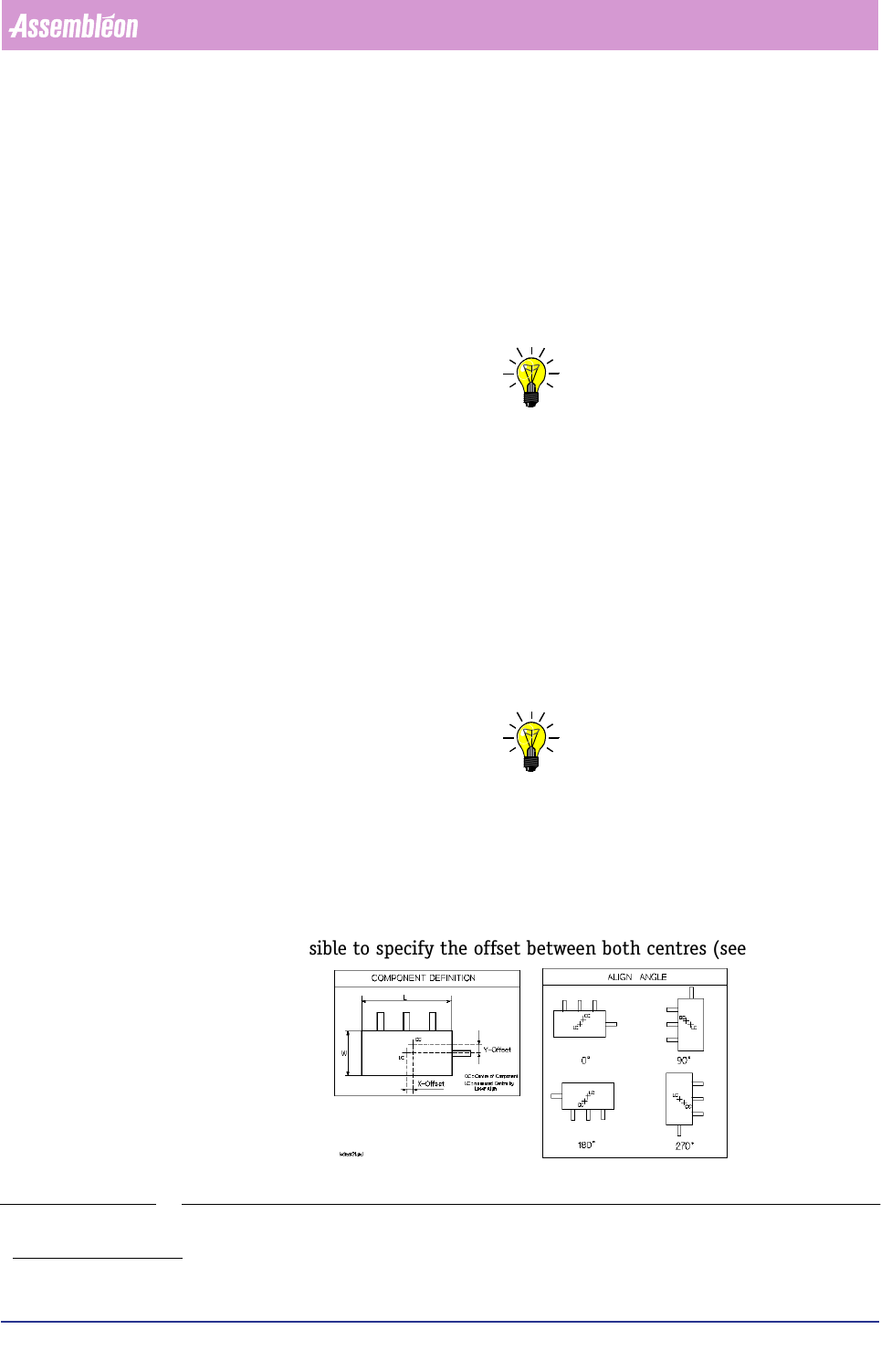
6.6.6 Component Offsets
When using assymmetrical components, component offsets in X, Y, and Phi
direction can be specified.
If the component’s body centre does not match its overall centre (body including
leads), it is possible to specify the offset between both centres (see FIGURE 6-17).
FIGURE 6-17 Assymmetrical component
1. Length and width, including tolerances.
Product Change Over
User Reference Manual 4022 591 96082
6-50 FCM Multiflex 02.02
6.7 WVM
6.7.1 Introduction
In order to be able to align a component by vision alignment, i.e. alignment by
using the camera unit, it is necessary to have all relevant information concerning
this component available.
For each package type, this information is available in an SMD information file, the
so-called “SMD info file”. This file consists of a number of ASCII lines that define
the various parameters.
The FCM Multiflex package type database you received with your FCM Multiflex
software package contains SMD info files for the most commonly used component
package types, ranging from type 0402 up to SO16. For more information on this
SMD info file type, see the chapter SMD Info Files in the Service Manual FCM
Multiflex.
6.7.2 General Information on Component Package Parameters
6.7.2.1 Introduction
In this section, all relevant aspects that play a role within the SMD info file
parameters description are explained. Exact definitions are given here to avoid
confusion while manipulating components and interpreting results.
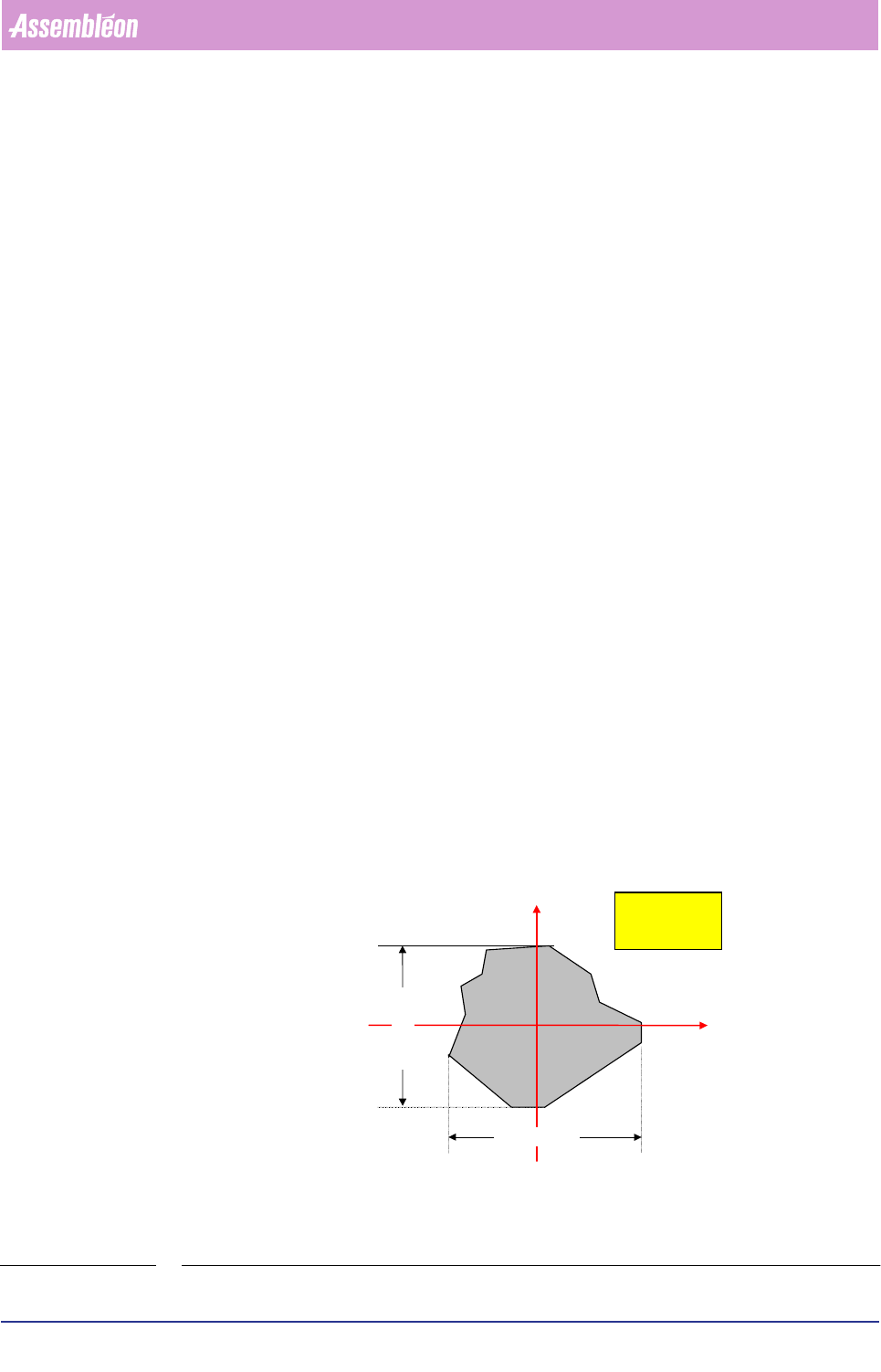
6.7.2.2 Package Orientation Aspects Definitions
Component Coordinate System
The relationship between the component coordinate system (wind directions) and
the machine coordinate system (X,Y coordinates) is shown in the figure below
(FIGURE 6-18)
.
FIGURE 6-18 Component orientation (wind directions) related to machine orientation (X,Y coordi-
nates)
X
Y
North
EastWest
South
X-dimension
Y-dimension
view from
above