FCM_User Reference Manual.pdf.pdf - 第243页
4022 591 960 82 Us er Reference Man ual 02.02 FC M Multif lex 6-51 Pr oduc t Ch ang e Ov er Component Side Definition T o c l e a r l y , u n i v o c a l l y d e f i n e w h a t i s e . g . t h e c o m p o n e n t ’ s NO…
Product Change Over
User Reference Manual 4022 591 96082
6-50 FCM Multiflex 02.02
6.7 WVM
6.7.1 Introduction
In order to be able to align a component by vision alignment, i.e. alignment by
using the camera unit, it is necessary to have all relevant information concerning
this component available.
For each package type, this information is available in an SMD information file, the
so-called “SMD info file”. This file consists of a number of ASCII lines that define
the various parameters.
The FCM Multiflex package type database you received with your FCM Multiflex
software package contains SMD info files for the most commonly used component
package types, ranging from type 0402 up to SO16. For more information on this
SMD info file type, see the chapter SMD Info Files in the Service Manual FCM
Multiflex.
6.7.2 General Information on Component Package Parameters
6.7.2.1 Introduction
In this section, all relevant aspects that play a role within the SMD info file
parameters description are explained. Exact definitions are given here to avoid
confusion while manipulating components and interpreting results.
6.7.2.2 Package Orientation Aspects Definitions
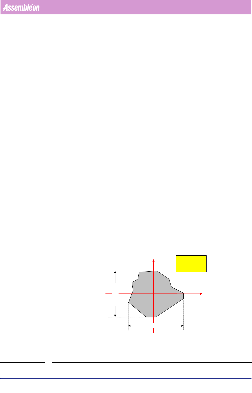
Component Coordinate System
The relationship between the component coordinate system (wind directions) and
the machine coordinate system (X,Y coordinates) is shown in the figure below
(FIGURE 6-18)
.
FIGURE 6-18 Component orientation (wind directions) related to machine orientation (X,Y coordi-
nates)
X
Y
North
EastWest
South
X-dimension
Y-dimension
view from
above
4022 591 96082 User Reference Manual
02.02 FCM Multiflex 6-51
Product Change Over
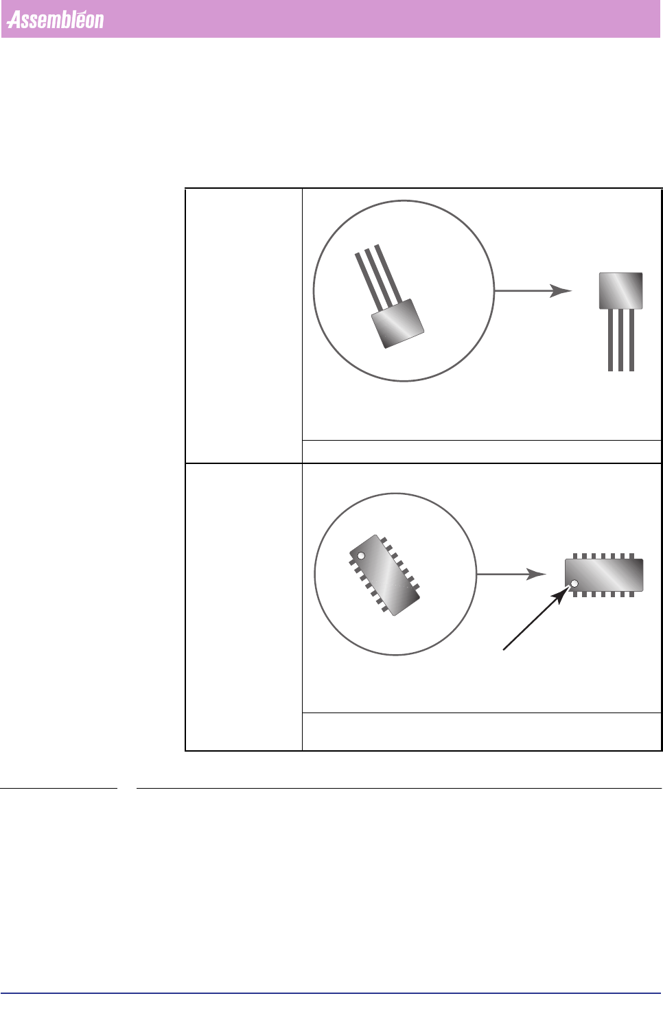
Component Side Definition
To clearly, univocally define what is e.g. the component’s NORTH side, EAST side
etc., following applies:
TABLE 6-21
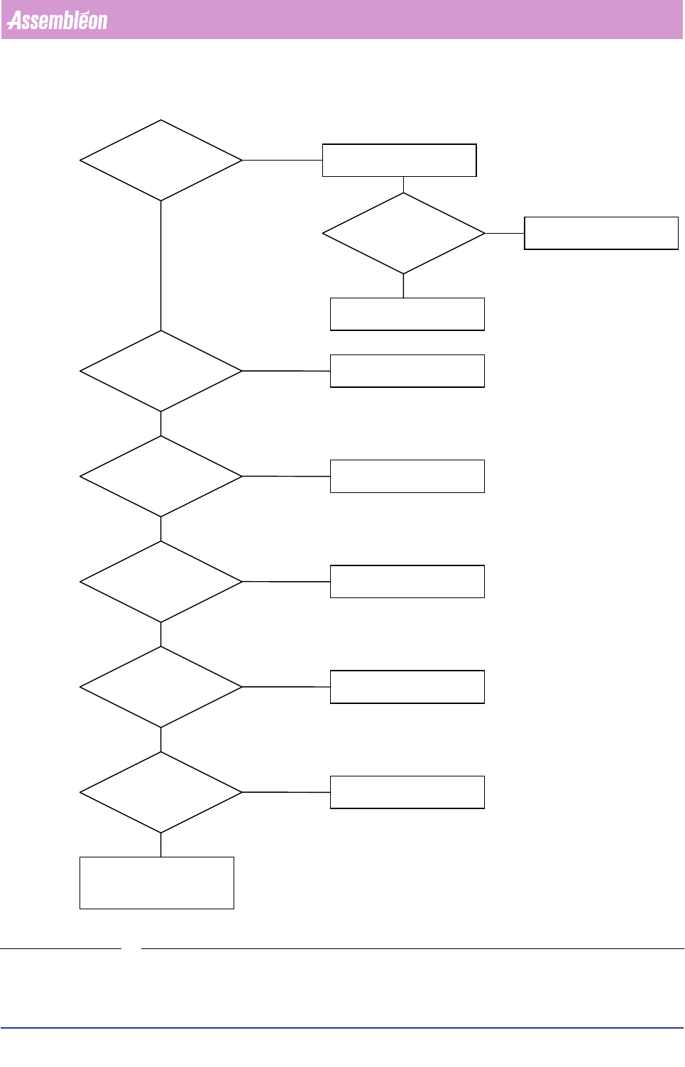
For other cases, use following determination flow diagram (FIGURE 6-19).
Components with
leads at one side
lead side is SOUTH
Components with
leads at both the
opposite sides;
number of leads > 1
lead sides are NORTH and SOUTH; if a marker is present, it’s explic-
itely indicating the SOUTH side
S
?
?
N
S
marker
Product Change Over
User Reference Manual 4022 591 96082
6-52 FCM Multiflex 02.02
FIGURE 6-19 Component side determination flow diagram
component has 1 lead on
only two opposite sides ?
component has
orientation marker
on corner ?
component has
(electrical) reference
lead 1 on corner ?
component has
polarity marker ?
Yes
Yes
Yes
Yes
Leads EAST-WEST
polarity marker is
WEST
No
No
No
marker is
SOUTH-WEST
lead 1 is
SOUTH-WEST
longest side EAST-WEST,
NORTH-SOUTH
unim
p
ortant
leads are SOUTH
only leads
at one side ?
Yes
component has
orientation marker
on side ?
component has
(electrical) reference lead
1 on side ?
Yes
Yes
No
No
marker is
SOUTH
lead 1 is
SOUTH
distinction EAST/WEST
not important
No
No