FCM_User Reference Manual.pdf.pdf - 第244页
Pr oduc t Ch ang e Ov er User Re f eren ce Manu al 4022 591 960 82 6-52 FCM M ult ifle x 02.02 FI GURE 6-19 Compone nt sid e d etermin ati on flow d iag ram component has 1 lead on onl y tw o opp osi te si d es ? comp on…
4022 591 96082 User Reference Manual
02.02 FCM Multiflex 6-51
Product Change Over
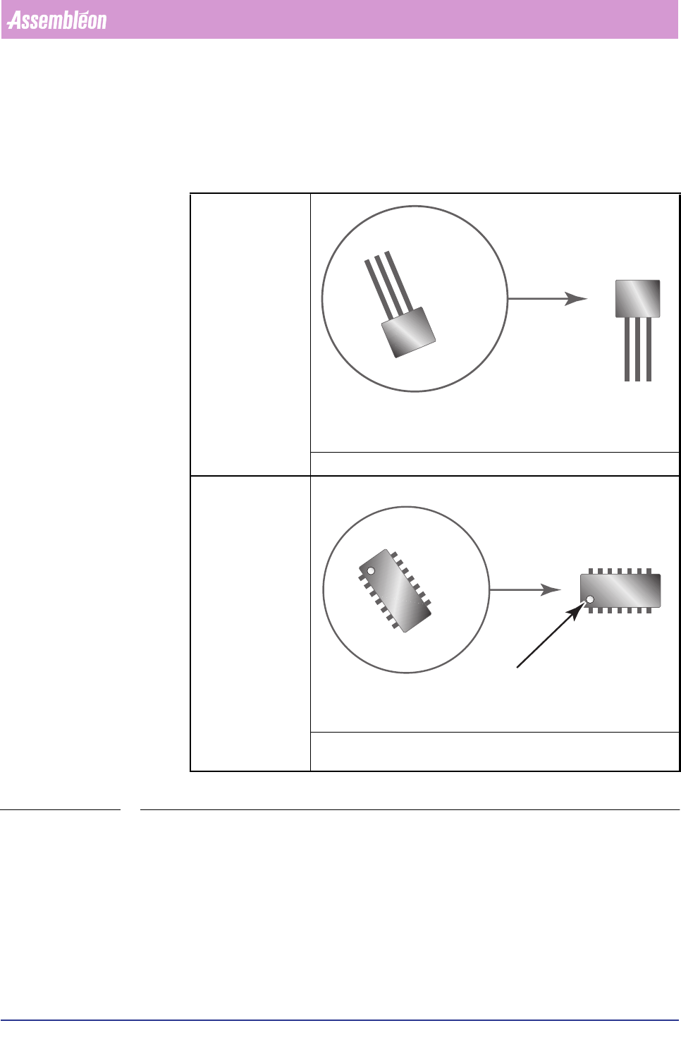
Component Side Definition
To clearly, univocally define what is e.g. the component’s NORTH side, EAST side
etc., following applies:
TABLE 6-21
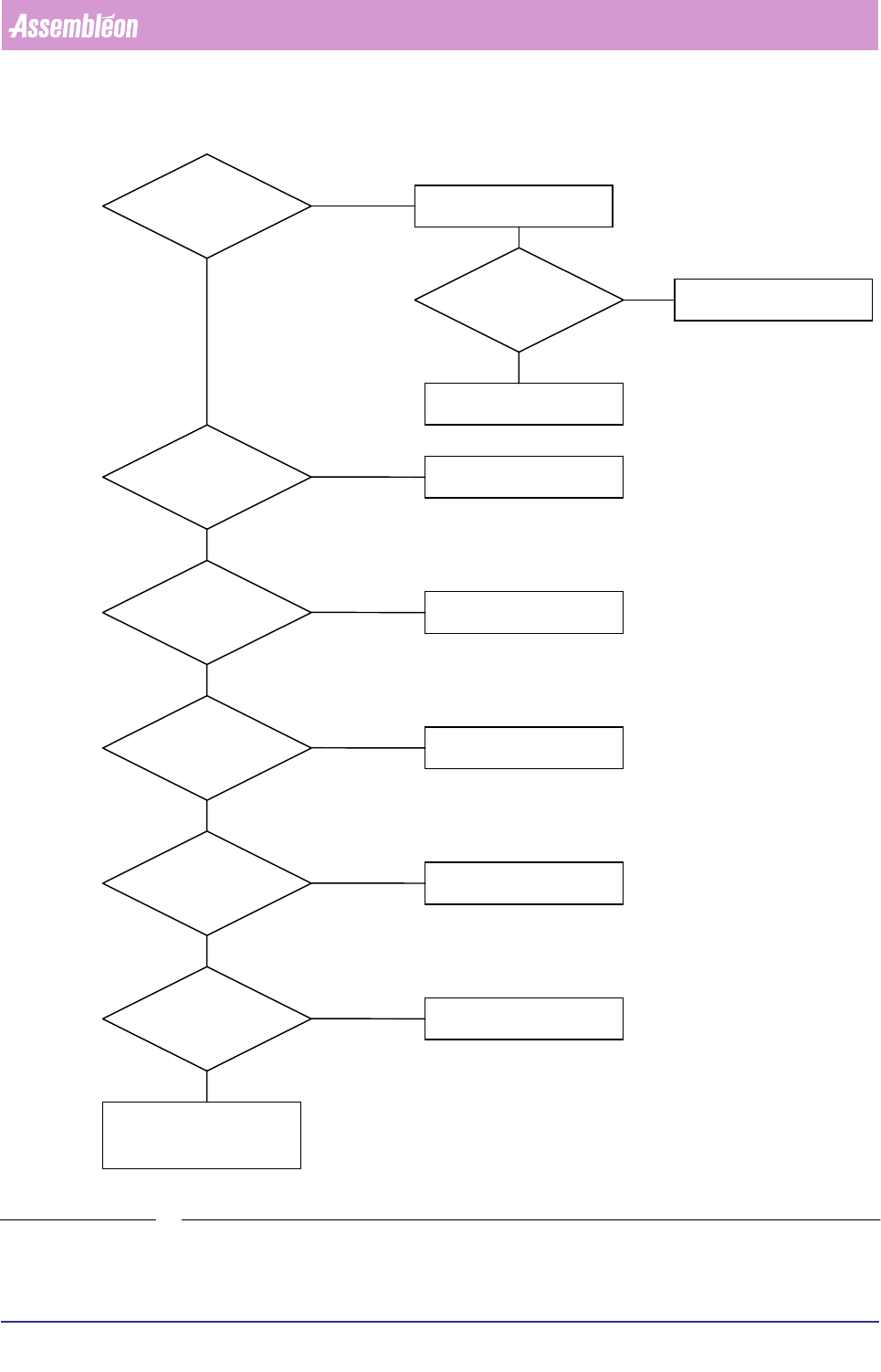
For other cases, use following determination flow diagram (FIGURE 6-19).
Components with
leads at one side
lead side is SOUTH
Components with
leads at both the
opposite sides;
number of leads > 1
lead sides are NORTH and SOUTH; if a marker is present, it’s explic-
itely indicating the SOUTH side
S
?
?
N
S
marker
Product Change Over
User Reference Manual 4022 591 96082
6-52 FCM Multiflex 02.02
FIGURE 6-19 Component side determination flow diagram
component has 1 lead on
only two opposite sides ?
component has
orientation marker
on corner ?
component has
(electrical) reference
lead 1 on corner ?
component has
polarity marker ?
Yes
Yes
Yes
Yes
Leads EAST-WEST
polarity marker is
WEST
No
No
No
marker is
SOUTH-WEST
lead 1 is
SOUTH-WEST
longest side EAST-WEST,
NORTH-SOUTH
unim
p
ortant
leads are SOUTH
only leads
at one side ?
Yes
component has
orientation marker
on side ?
component has
(electrical) reference lead
1 on side ?
Yes
Yes
No
No
marker is
SOUTH
lead 1 is
SOUTH
distinction EAST/WEST
not important
No
No
4022 591 96082 User Reference Manual
02.02 FCM Multiflex 6-53
Product Change Over
Component Length and Width
Once you have determined the component’s sides definition (see section before),
you have to know what component sides are defined as length respectively width.
See following table for determination.
TABLE 6-22
REMARK: Please note that according to this definition NOT the longest component
side automatically is defined as “ length” !
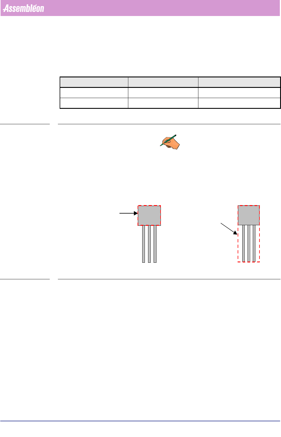
Component Body and Outline
Depending on the component type, measurements are done component package
body-based or component package outline-based. See FIGURE 6-20.
FIGURE 6-20 Component package’s body versus outline
&RPSRQHQWVLGH &RPSRQHQWRULHQWDWLRQ 0DFKLQHRULHQWDWLRQ
LENGTH WEST-EAST X-axis
WIDTH SOUTH-NORTH Y-axis
packag
e
outlin
e
package
bod
y