FCM_User Reference Manual.pdf.pdf - 第250页
Pr oduc t Ch ang e Ov er User Re f eren ce Manu al 4022 591 960 82 6-58 FCM M ult ifle x 02.02 number of leads at side north/south check leads ew number of leads at side east/wes t check thickne ss compone nt thickne ss …
4022 591 96082 User Reference Manual
02.02 FCM Multiflex 6-57
Product Change Over
6.7.3.2 Parameter Description
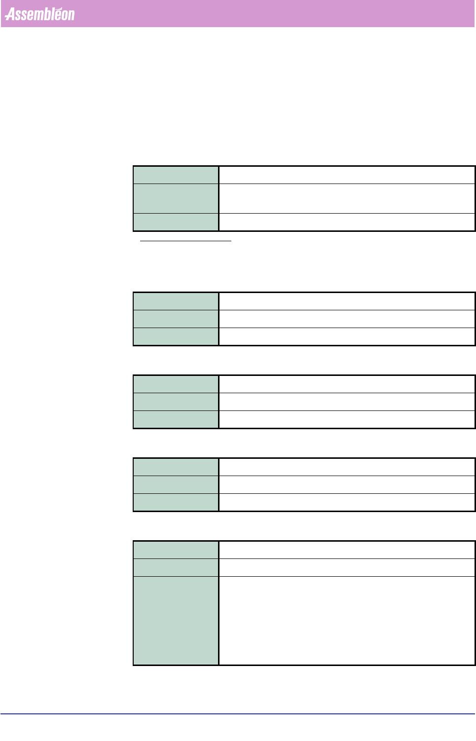
component type
This parameter consists of the two sub-parameters component name or component
code.
▼
component name
▼ component code
component length
component width
check leads ns
Field type Quoted string
Range
a
a. The option sign “|” indicates that one out
of the listed parameters is to be used.
“PLCC” | “QFP” | “SSOP” | “SOJ” | “TSOP” | “TSSOP” | “SO” | “VSO” |
“CLC_1210”
Description General name of the component type
Field type Integer
Range 1 - 19
Description Component’s name equivalent, represented as a number
Field type Real
Range 0 - 25.000 (mm)
Description Component’s nominal length
Field type Real
Range 0 - 25.000 (mm)
Description Component’s nominal width
Field type Integer
Range TRUE | FALSE(TRUE = 1; FALSE = 0)
Description If TRUE, then the vision system will check the number of leads at
both the north/south side as stated in the <number of leads at side
north/south> field.
If FALSE, then the vision system will count the number of leads at
each north/south side and check that both numbers match.
For components that don’t have north/south leads by component type
definition, this field is ignored.
Product Change Over
User Reference Manual 4022 591 96082
6-58 FCM Multiflex 02.02
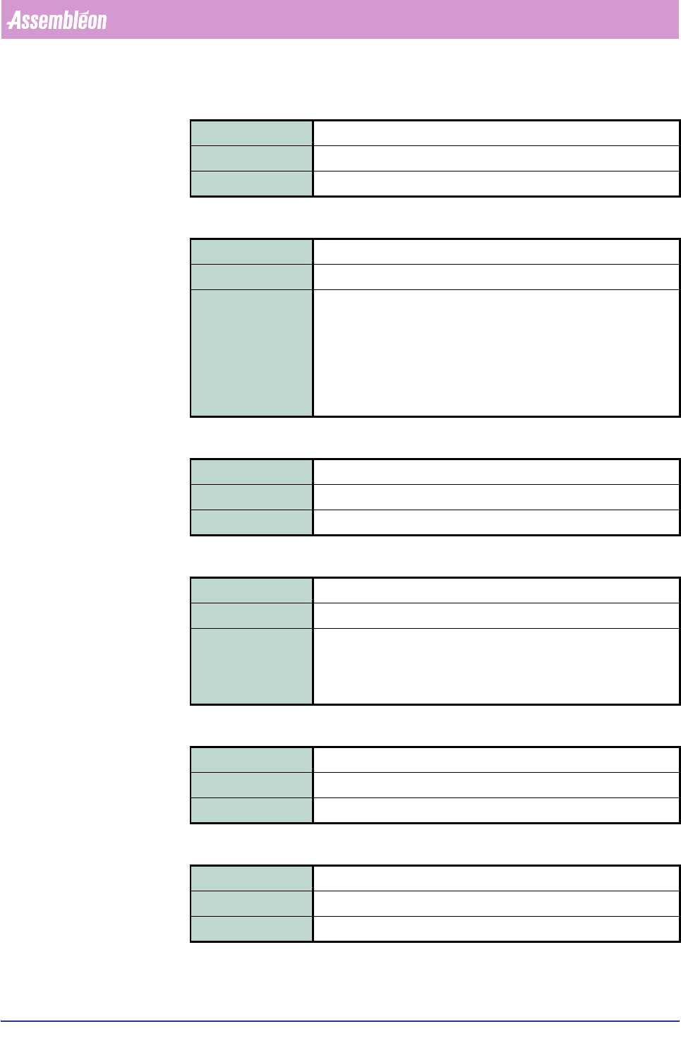
number of leads at side north/south
check leads ew
number of leads at side east/west
check thickness
component thickness
light level
Field type Integer
Range 0 - 100
Description Number of leads at each north/south side
Field type Integer
Range TRUE | FALSE
Description If TRUE, then the vision system will check the number of leads at
both the east/west side as stated in the <number of leads at side
east/west> field.
If FALSE, then the vision system will count the number of leads at
each east/west side and check that both numbers match.
For components that don’t have east/west leads by component type
definition, this field is ignored.
Field type Integer
Range 0 - 100
Description Number of leads at each east/west side
Field type Integer
Range TRUE | FALSE
Description If TRUE, then the vision system will use the value that is stated in the
<component thickness> field.
If FALSE, then the vision system will use a default value as defined
for the concerned component type.
Field type Real
Range 0.000 - 6.000 (mm)
Description Component thickness
Field type Integer
Range 0 - 100
Description Light level setting for an adequate measuring of the component.
4022 591 96082 User Reference Manual
02.02 FCM Multiflex 6-59
Product Change Over
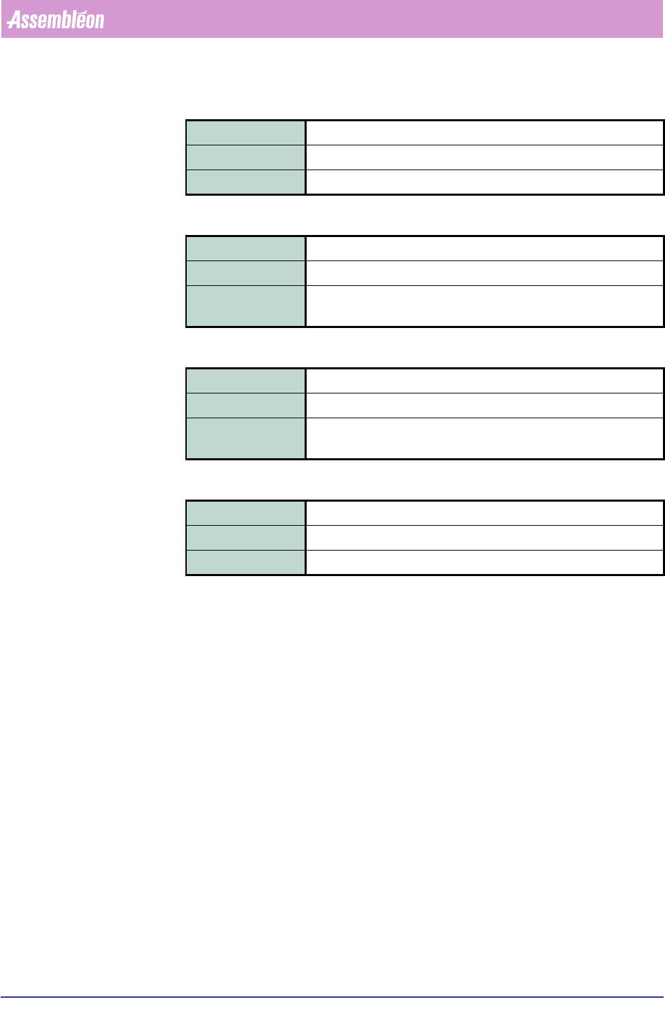
ruler threshold
maximum X offset
maximum Y offset
maximum PHI offset
Field type Integer
Range 0 - 255
Description Ruler threshold setting for an adequate measuring of the component.
Field type Real
Range 0 - 1.00 (mm)
Description Maximum permissible difference in X-direction between nominal
component centre line and measured component centre line.
Field type Real
Range 0 - 1.00 (mm)
Description Maximum permissible difference in Y-direction between nominal com-
ponent centre line and measured component centre line.
Field type Real
Range 0 - 6 (degrees)
Description Maximum permissible component rotation.