FCM_User Reference Manual.pdf.pdf - 第259页
4022 591 960 82 Us er Reference Man ual 02.02 FC M Multif lex 6-67 Pr oduc t Ch ang e Ov er ▼ GROUP_ OFFSET ▼ LEAD_WIDTH ▼ LEAD_PITCH Field type Real Range (mm) Description <group_offset_X> <group_of fset_Y> …
Product Change Over
User Reference Manual 4022 591 96082
6-66 FCM Multiflex 02.02
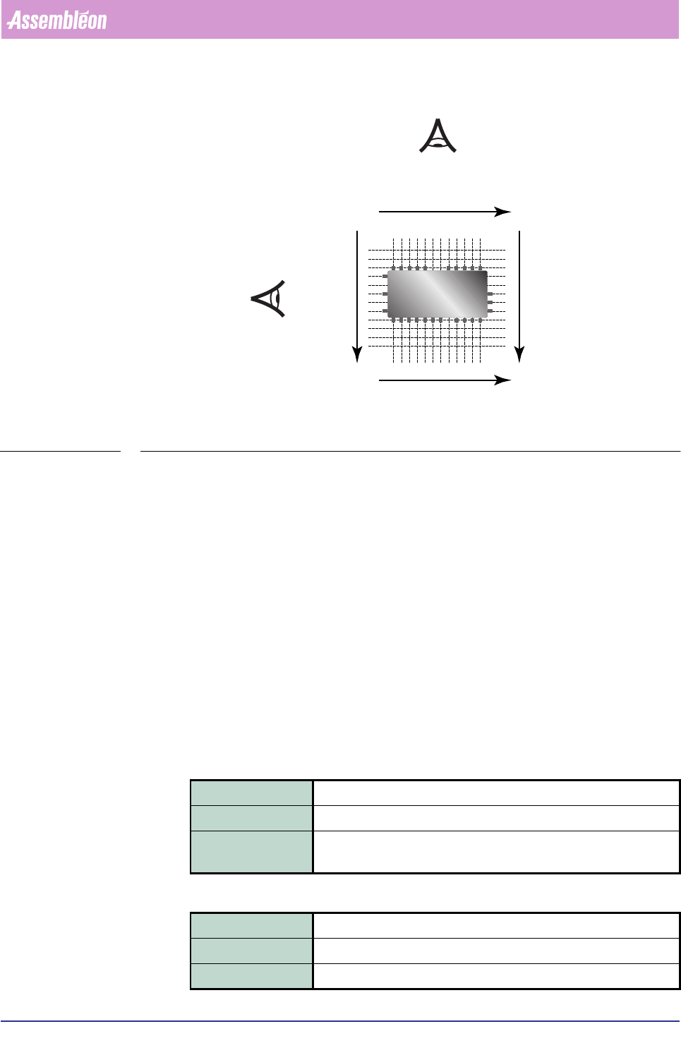
FIGURE 6-26 Numbering sequences as used within the lead information blocks
Each lead-side block can contain the following parameters:
• NB_OF_LEAD_GROUPS
• NB_OF_LEADS (NB_OF_LEADS_i if i>1)
• GROUP_OFFSET (GROUP_OFFSET_i if i>1)
• LEAD_WIDTH (LEAD_WIDTH_i if i>1)
• LEAD_PITCH (LEAD_PITCH_i if i>1)
• LEAD_LENGTH (LEAD_LENGTH_i if i>1)
• LEAD_TOLERANCE (LEAD_TOLERANCE_i if i>1)
An SMD info file may contain more than one lead group parameter block. Which
blocks are present depends on the package class, e.g. an SMD info file for a
component of the SOT package class contains a [NORTH] and a [SOUTH] block. Each
parameter block consists of two sets of sub-parameters.
▼
NB_OF_LEAD_GROUPS
▼ NB_OF_LEADS
Field type Integer
Range 0 - 255
Description Defines the number of lead groups (group of leads with identical
pitch) for a component side.
Field type Integer
Range 1 - 255
Description Defines the number of leads in a specific lead group.
North
South
West
East
1
1
1
1
1
1
4022 591 96082 User Reference Manual
02.02 FCM Multiflex 6-67
Product Change Over
▼ GROUP_OFFSET
▼ LEAD_WIDTH
▼ LEAD_PITCH
Field type Real
Range (mm)
Description <group_offset_X> <group_offset_Y>
Defines the offset of a lead group with respect to the centre of the
component.
Field type Real
Range > 0 (mm)
Description Defines the width of the leads in a lead group.
a
a. If leads are involved, the vision
system’s measurement may deviate from the
mechanical lead width; see NOTE under
“LEAD_LENGTH”.
Field type Real
Range > 0 (mm)
Description Defines the distance between the centres of two adjacent leads.
Product Change Over
User Reference Manual 4022 591 96082
6-68 FCM Multiflex 02.02
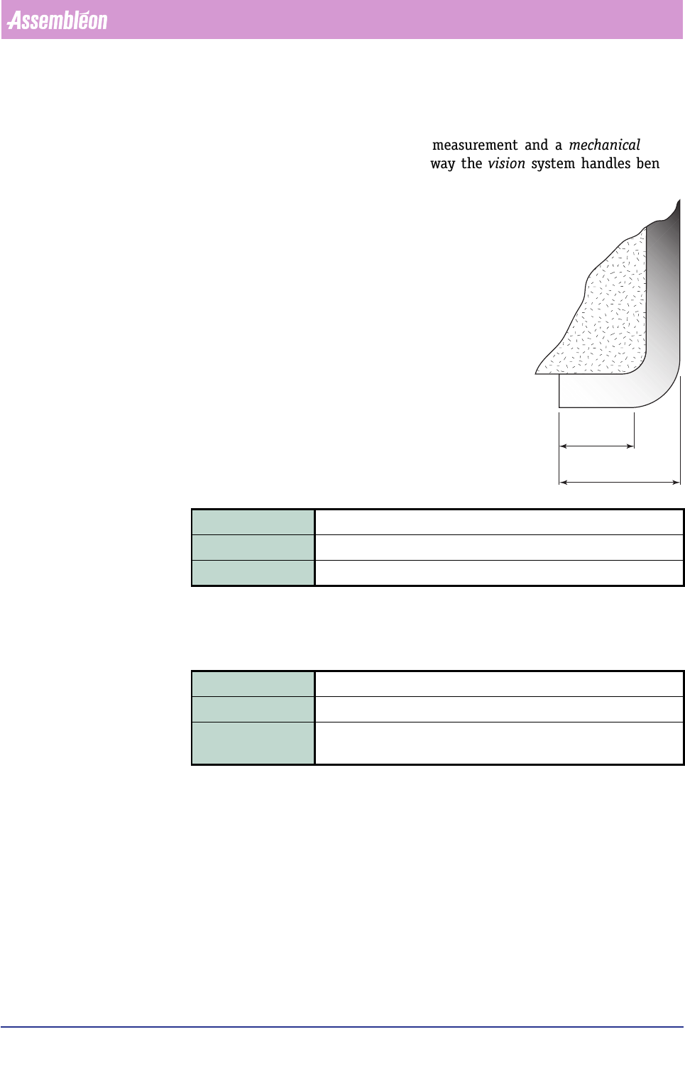
▼ LEAD_LENGTH
This parameter defines the length of the leads as they will be measured by the
vision system. A discrepancy between this measurement and a mechanical meas-
urement may be possible as a result of the way the vision system handles bent or
curved leads; see figure below.
▼
LEAD_TOLERANCE
This parameter defines the maximum allowable difference in lead pitch, or in case
of only one lead, it represents the tolerance on the lead width.
Vision Processing Parameters
Vision processing parameters are the (dedicated) parameters which are valid for all
lead groups on that side, and are used to tune the detection algorithm.
Each lead group parameter block can contain the following parameters:
• RULER_THRESHOLD
• RULER_WIDTH
• RULER_OFFSET
Field type Real
Range > 0 (mm)
Description Defines the length of the leads in a lead group; see above NOTE.
Field type Real
Range > 0 (mm)(rule of thumb: < 50% of the lead width)
Description If NB_OF_LEADS > 1, then it represents the tolerance on the OHDG
SLWFK, else it represents the tolerance on the OHDGZLGWK.
measured
by vision
mechanical
measure
NOTE:
Between a mechanical lead length
measurement and the vision
measurement, relative
considerable deviations may occur
(see figure).
For
symmetric
components, these
differences are compensated for by
the averageing effect from the
opposite component side result.
However, for
asymmetric
components, there is no averaging
effect, and this will have its
influence on alignment.