FCM_User Reference Manual.pdf.pdf - 第268页
Pr oduc t Ch ang e Ov er User Re f eren ce Manu al 4022 591 960 82 6-76 FCM M ult ifle x 02.02 LEAD_TOLERANCE_2 0.800 NB_OF_ LEADS_3 3 GROUP_O FFSET_3 3.233 3.050 LEAD_WID TH_3 0 .450 LEAD_PIT CH_3 1.600 LEAD_LENGTH_3 1 …

4022 591 96082 User Reference Manual
02.02 FCM Multiflex 6-75
Product Change Over
NB_OF_LEADS 11
GROUP_OFFSET -6.35 8.4
LEAD_WIDTH 0.45
LEAD_PITCH 1.27
LEAD_LENGTH 0.60
LEAD_TOLERANCE 0.20
RULER_THRESHOLD 20
RULER_WIDTH 3
RULER_OFFSET 7
SPECIAL: TOKO50X3
[GENERAL]
CREATOR PTDB
ISSUEDATE 98-02-26
SYNTAX 202
[PACKAGE]
PACKAGE_CLASS SPECIAL
BODY_DIMENSION 14.500 6.100 4.8000.000
REJECT_LEVEL 3.000 3.000 30.000
BODY_TOLERANCE 2.000 2.000
[2D]
ILLUMINATION_TYPE TRANSMISSION
LIGHT_LEVEL 50
[NORTH]
NB_OF_LEAD_GROUPS 3
NB_OF_LEADS 3
GROUP_OFFSET -6.433 3.050
LEAD_WIDTH 0.450
LEAD_PITCH 1.600
LEAD_LENGTH 1.200
LEAD_TOLERANCE 0.800
NB_OF_LEADS_2 3
GROUP_OFFSET_2 -1.600 3.050
LEAD_WIDTH_2 0.450
LEAD_PITCH_2 1.600
LEAD_LENGTH_2 1.200

Product Change Over
User Reference Manual 4022 591 96082
6-76 FCM Multiflex 02.02
LEAD_TOLERANCE_2 0.800
NB_OF_LEADS_3 3
GROUP_OFFSET_3 3.233 3.050
LEAD_WIDTH_3 0.450
LEAD_PITCH_3 1.600
LEAD_LENGTH_3 1.200
LEAD_TOLERANCE_3 0.800
RULER_THRESHOLD 18
RULER_WIDTH 1
RULER_OFFSET 1
[SOUTH]
NB_OF_LEAD_GROUPS 3
NB_OF_LEADS 2
GROUP_OFFSET -6.433 -3.050
LEAD_WIDTH 0.450
LEAD_PITCH 3.200
LEAD_LENGTH 1.200
LEAD_TOLERANCE 0.800
NB_OF_LEADS_2 2
GROUP_OFFSET_2 -1.600 -3.050
LEAD_WIDTH_2 0.450
LEAD_PITCH_2 3.200
LEAD_LENGTH_2 1.200
LEAD_TOLERANCE_2 0.800
NB_OF_LEADS_3 2
GROUP_OFFSET_3 3.233 -3.050
LEAD_WIDTH_3 0.450
LEAD_PITCH_3 3.200
LEAD_LENGTH_3 1.200
LEAD_TOLERANCE_3 0.800
RULER_THRESHOLD 18
RULER_WIDTH 1
RULER_OFFSET 1
4022 591 96082 User Reference Manual
02.02 FCM Multiflex 6-77
Product Change Over
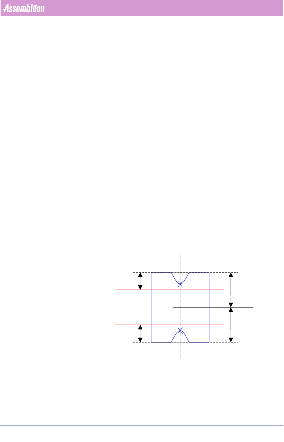
6.7.4.4 Used Measuring Algoritms
The RECTANGLE algorithm
▼ How does it work
1. Find the rough centre and angle of the reflecting areas.
2. Measure the North-South vertical size and centre.
3. Measure the North and South horizontal size, and update the position of the
horizontal centre of the component with these measured values.
4. Check the component’s vertical and horizontal size, and place rulers. The rulers
will be placed on the following positions: The center of the component found by
step 2 and 3, incremented by the vertical size - or horizontal size, depending on
the component’s orientation - divided by two, and decremented by the ruler
offset.
5. Execute a vertical or a horizontal optimization, depending on whether the
component is a vertical or a horizontal rectangle, see below.
▼
Vertical optimization
The most Northern and the most Southern position will be measured at which hori-
zontal rulers will be drawn. Now the optimized centre and angle are calculated.
▼
Horizontal optimization
The most Eastern and the most Western position will be measured at which vertical
rulers will be drawn. Now the optimized centre and angle are calculated.
FIGURE 6-27 The RECTANGLE algorithm measuring aspects
Ruler
Ruler
Ruler-offset
Ruler-offset
Vertical size / 2
Vertical size / 2
NORTH
SOUTH