FCM_User Reference Manual.pdf.pdf - 第280页
Pr oduc t Ch ang e Ov er User Re f eren ce Manu al 4022 591 960 82 6-88 FCM M ult ifle x 02.02 The SPECIA L algorithm ▼ H o w does it work 1. F or the “ fir st sid e ” (as de fine d in the SMD inf o fil e), fin d th e fi…
4022 591 96082 User Reference Manual
02.02 FCM Multiflex 6-87
Product Change Over
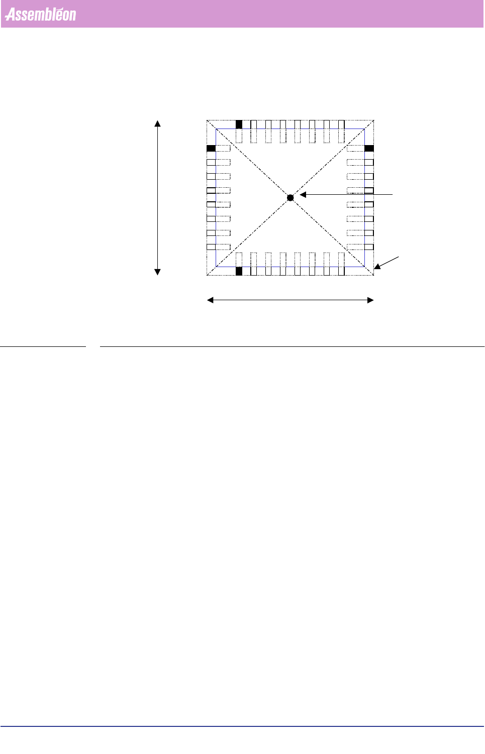
8. Calculate the component origin, based on the found vision origin and gravity
offsets.
FIGURE 6-38 Calculation of the component’s origin
▼
For which components do you use this algorithm
For components that have leads on all four sides, and of which the leads are bent
underneath the body (J-leads) and only one lead group a side, like:
• PLCC44.
▼
General important information
• Ruler offsets are adjustable in the SMD info file; normally the value 3 is used
for most components (5 or 7 is also possible if you have components with a
bigger lead width). Ruler offset is in pixels; one pixel = 75x 75 µm. Always
use odd ruler widths in order to get valid mean calculation results.
• The body length and width in the SMD info file must be correct, because they
determine the positions of the leads together with the number of leads and
the lead pitch.
• For the ruler threshold, the value is normally between 20 and 30, but it
depends on the specific component type and the amount of light used.
• The search area as indicated in the drawings matches the reject level in the
SMD info file.
• If you want to use the skew angle option, you have to use the SPECIAL
algorithm.
Component origin = vision origin
Component outline
NORTH
WEST
EAST
SOUTH
Body length
Body width
Product Change Over
User Reference Manual 4022 591 96082
6-88 FCM Multiflex 02.02
The SPECIAL algorithm
▼ How does it work
1. For the “first side” (as defined in the SMD info file), find the first lead of the
first lead group with a defined search area, and find the last lead of the last lead
group with a fine-search area.
2. If there is more than one side, find the first lead of the first lead group and find
the last lead of the last lead group for the other side(s).
3. Measure all lead sides (edges) for all component sides (North/South/East, or
West).
4. Measure all lead ends for all component sides (only for components that have
leads on only one or two sides).
5. Check the lead pitch (if there is more than one lead a side) for each lead group.
6. Calculate the centre and angle of the component origin with the information of
the lead sides and/or lead ends.
7. If skew-angle check is required, measure the skew angle of the 4-sided
component. Adjustable using the NT editor. (See QFP algorithm.)
8. Depending on the component type, check the distance between the middle of
the first side (North) to the middle of the second side (South) and between the
third side (East) and the fourth side (West).
9. Calculate the component origin, based on the found vision origin and gravity
offsets.
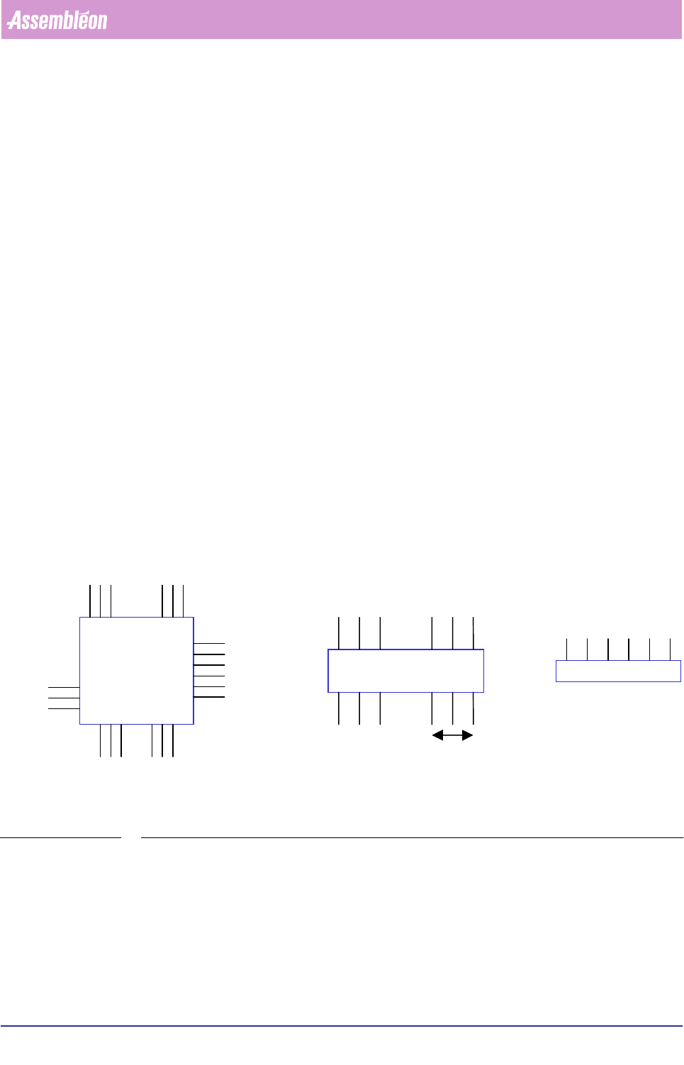
FIGURE 6-39
▼
For which components do you use this algorithm
For components with leads for which other algorithms cannot be used, like:
• Special QFPs;
• Connectors;
• SOs, QFPs, and PLCCs that have more than one lead group a side;
• D-Packs.
NORTH
SOUTH
EASTWEST
Lead-group

4022 591 96082 User Reference Manual
02.02 FCM Multiflex 6-89
Product Change Over
▼ General important information
• Ruler offsets are adjustable in the SMD info file; normally the value 3 is used
for most components (5 or 7 is also possible if you have components with a
bigger lead width). Ruler offset is in pixels; one pixel = 75x 75 µm. Always
use odd ruler widths in order to get valid mean calculation results.
• The body length and width in the SMD info file must be correct, because they
determine the positions of the leads together with the number of leads and
the lead pitch.
• For the ruler threshold, the value is normally between 20 and 30, but it
depends on the specific component type and the amount of light used.
• The search area as indicated in the drawings matches the reject level in the
SMD info file.
• With this algorithm, you can describe more lead groups a side (North/South/
East/West).
• You can enable/disable the skew angle detection by using the NT editor. (For
details about skew angle detection, see QFP algorithm.)